DECAN_S2_Admin(Eng_Ver4.5).pdf - 第162页
6-49 Board Definition <4. Block Po sition> group When Block PCB type i s selected in the <Model T y pe > combo box; The offset coordinate of the plac e ment origin o f each block is indi cated. Select <S…
6-48
Advanced Chip Shooter DECAN S2 Administrator’s Guide
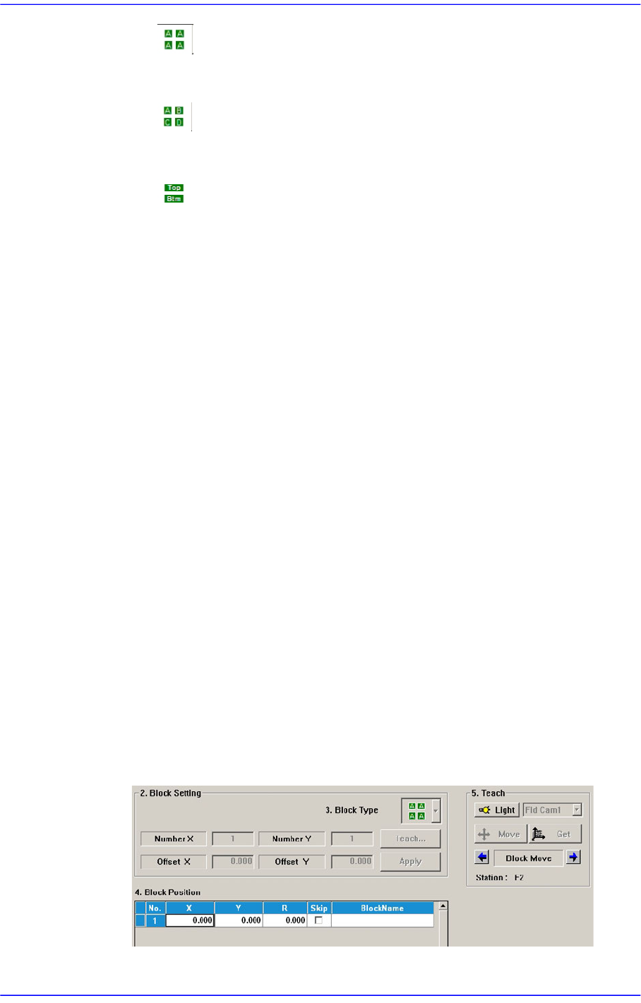
[Block PCB - Same Type]
The CAD information (placement point and part) on the block is identical.
[Block PCB - Different Type]
The CAD information (placement point and part) on the block is different.
[Block PCB - Top/Bottom Type]]
The CAD information (placement point and part) on the block is different.
When the Block PCB type is selected in the <Block Type> combo box
Perform setup for the block in the same manner as performing setup for an array PCB.
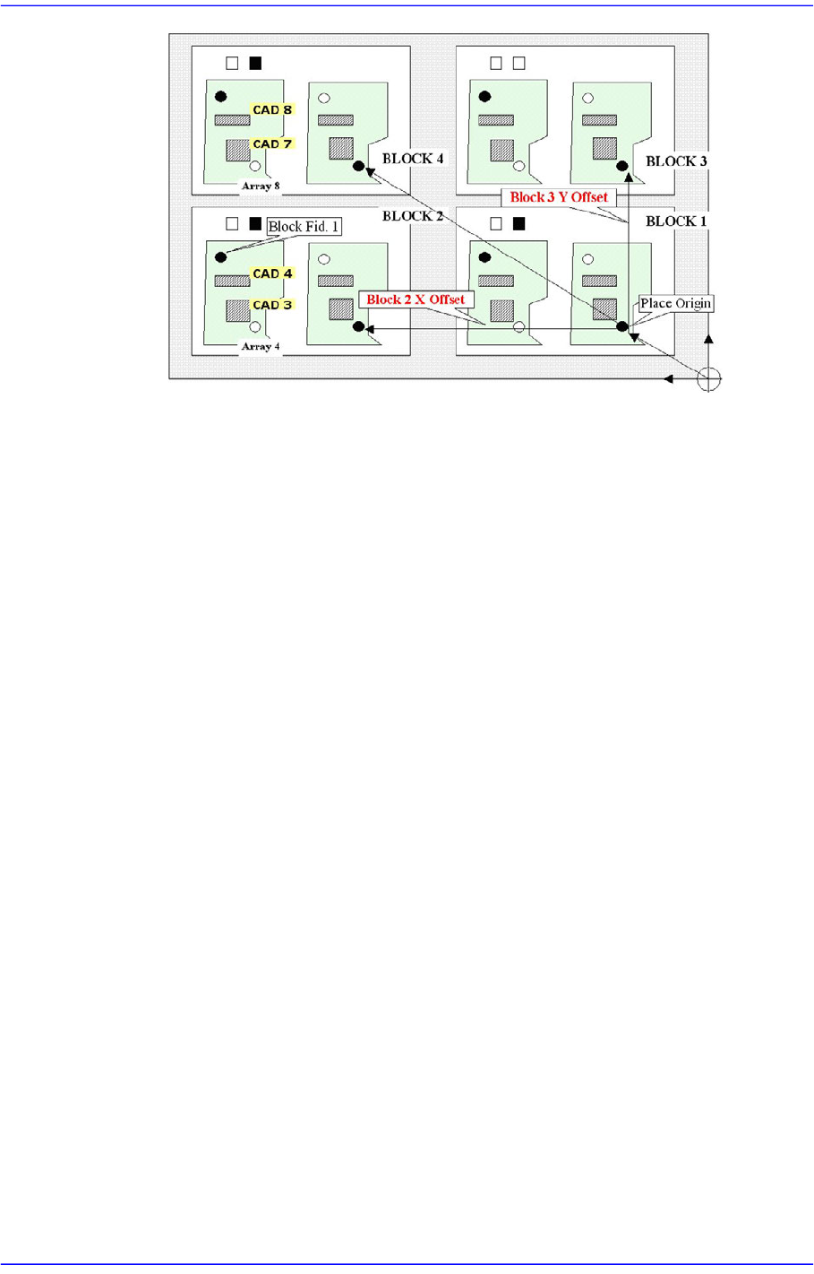
First, determine the number of blocks to be configured and apply the offset for the
placement origin of the reference block to set the placement origin of the entire block.
<Number X> edit box
Input the number of blocks in the X direction.
<Number Y> edit box
Input the number of blocks in the Y direction.
<Offset X> edit box
Input the offset in the X direction based on the placement origin of the existing
block.
<Offset Y> edit box
Input the offset in the Y direction based on the placement origin of the existing
block.
<Teach...> button
Teach the XY offset based on the placement origin of the existing block..
<Apply> button
Creates the data in the <3.Model Position> group according to the number of X
and Y blocks as well as the X and Y offset.
6-49
Board Definition
<4. Block Position> group
When Block PCB type is selected in the <Model Type> combo box;
The offset coordinate of the placement origin of each block is indicated. Select <Skip>
column when placement is not performed for the corresponding block.
The procedure to teach the placement origin offset of each block
Select the fiducial camera corresponding to the workstation to which the block
PCB is transferred.
Select the placement origin offset of the block in the <3. Model Position> group.
Click the <Move> button to move to the currently set position.
Click the <Get> button to input the current coordinate.
<Update> button
Saves the PCB model related setup data and closes the “PCB Model” dialog box.
<Cancel> button
Closes the “PCB Model” dialog box without saving the PCB model related setup data.
6-50
Advanced Chip Shooter DECAN S2 Administrator’s Guide
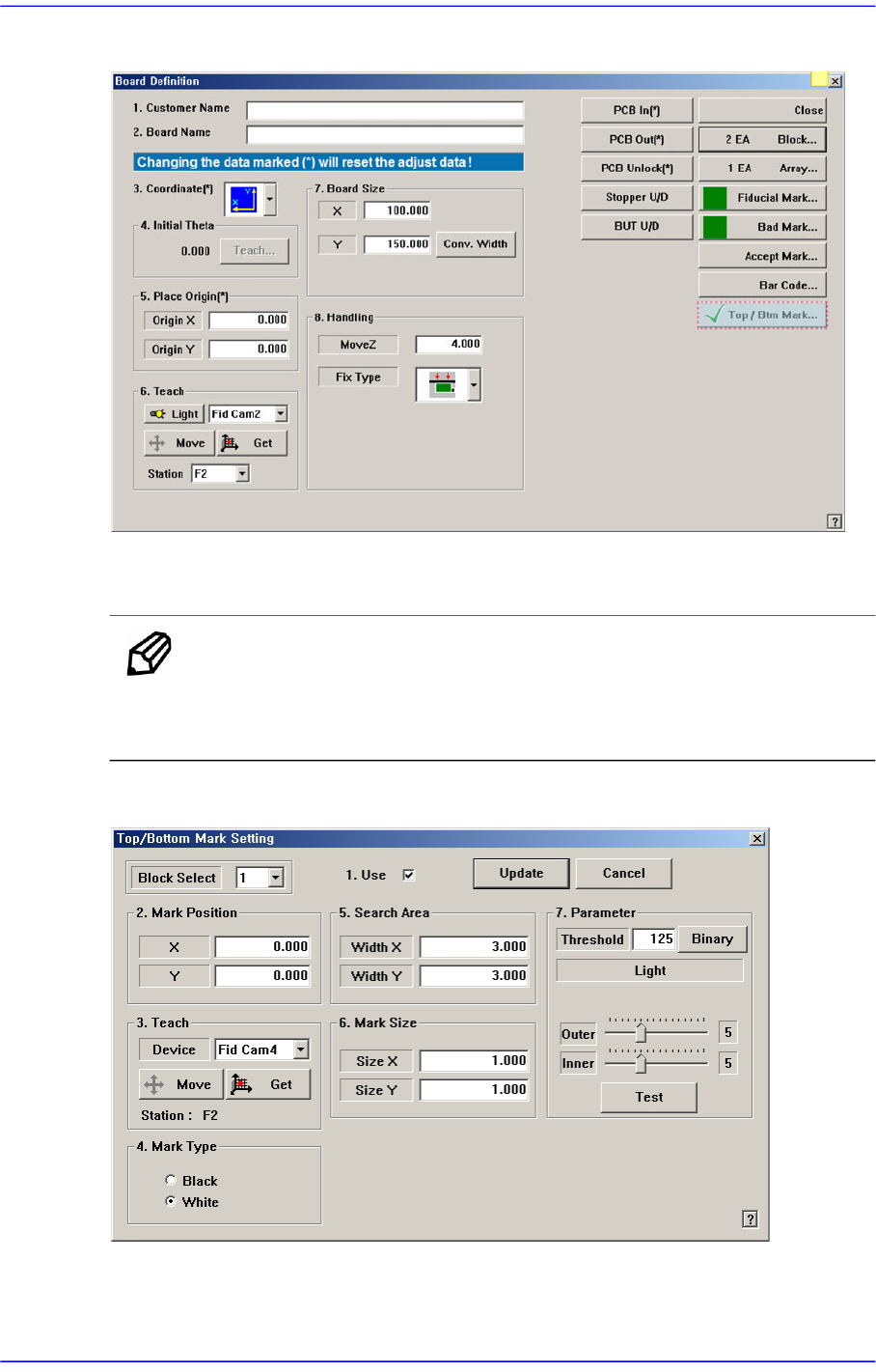
When the Block PCB type is selected in the <Top / Bottom Type> combo box
If you click on the <Top / Btm Mark ...> button, a dialog box similar to the following to set
the model type of PCB appears.
Memo In <3. Block Type> combo box of <PCB Block> dialog box, If you
select the Top / Bottom Type in the combo box, will enable the <Top /
Btm Mark ...> button.
Figure6.13 “Top / Bottom Mark Setting” dialog box
<Block Select> combo box
For a Multi PCB