DECAN_S2_Admin(Eng_Ver4.5).pdf - 第462页
15-11 System Setup When the air shower option is applied, set the s y stem dump box in the following manner : 1. Execute the S ystem Dump tab dialog box according to the order as s hown in the following figure. 2. Instal…
15-10
Advanced Chip Shooter DECAN S2 Administrator’s Guide
15.2.2. <System Dump> tab dialog
Sets the data related to the dump box where picked components are dumped.
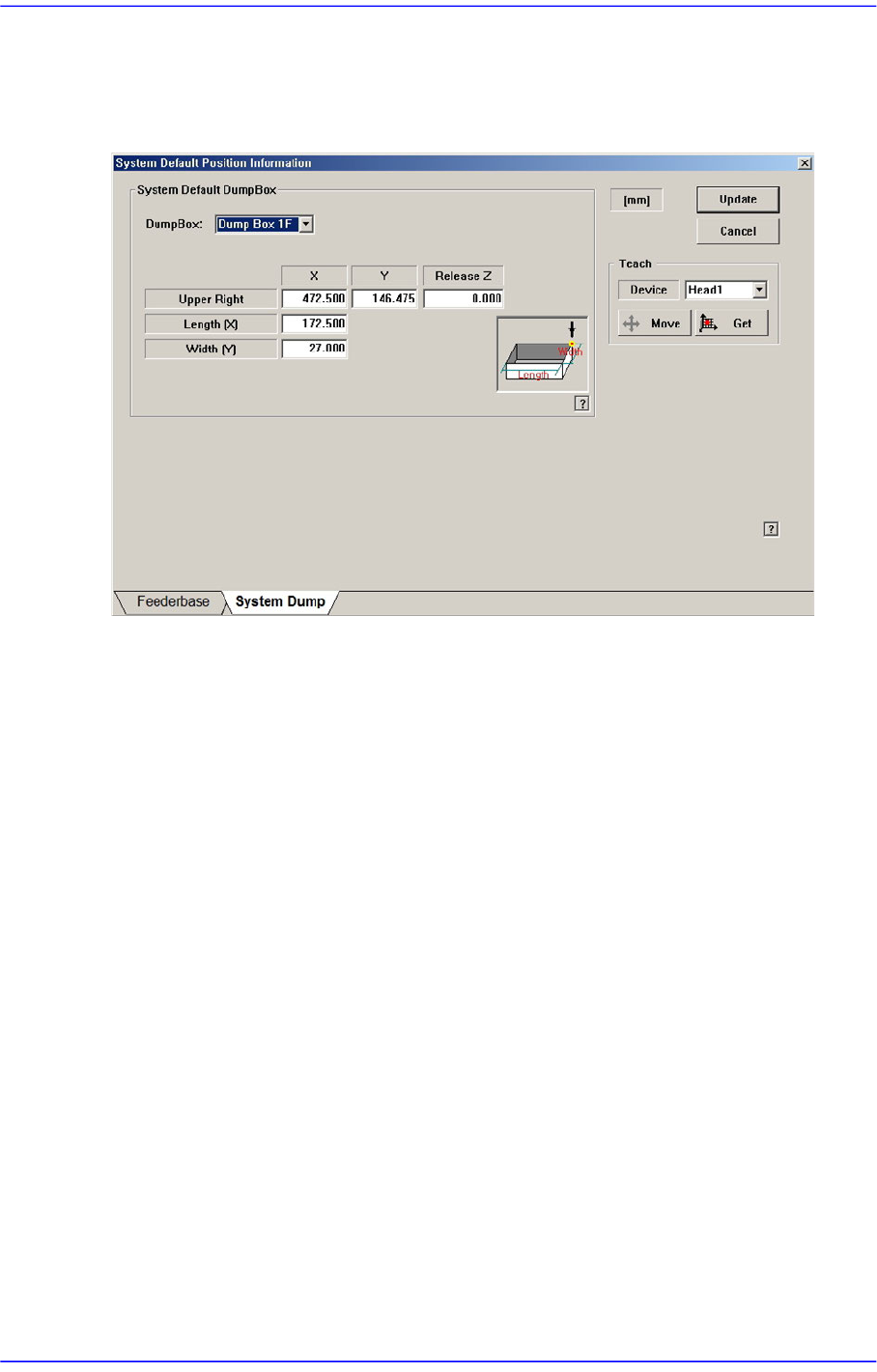
Figure15.6 “System Dump” tab dialog
<System Default Dump Box> group
Inputs the position of the system dump box.
<Dump Box> combo box
Select the dump box to be set.
<Position - X, Y> edit box
Sets the X and Y positions of the head when dumping the components. Teach the
position (dump box center) at which parts are dumped.
<Release Z > edit box
Sets the Z axis of the head spindle when dumping parts.
<Length [X] > edit box
Inputs the dump box length.
<Width [Y] > edit box
Inputs the dump box height.
<Update> button
Transmits the set data to the equipment and closes the dialog box.
<Cancel> button
Ignores the set data and closes the dialog box.
15-11
System Setup
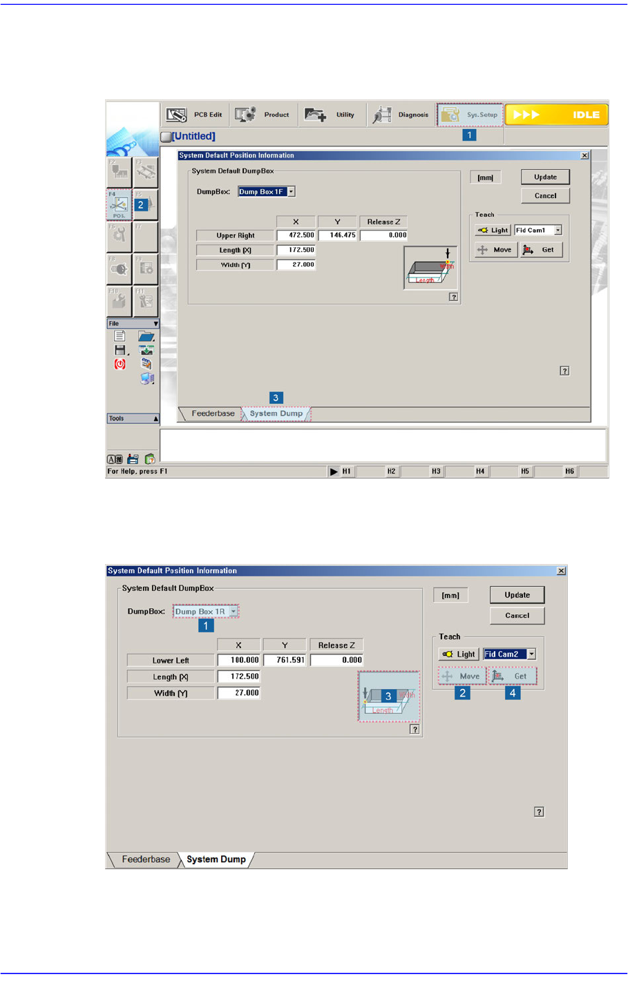
When the air shower option is applied, set the system dump box in the following manner:
1. Execute the System Dump tab dialog box according to the order as shown in the
following figure.
2. Install the dump box at a dump box position of the front conveyor.
3. Move the Fid Cam1 to the No.3 position in the following figure using the jog box and
click the <Get> button to teach the coordinate.
15-12
Advanced Chip Shooter DECAN S2 Administrator’s Guide
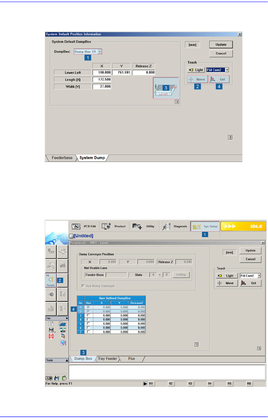
4. Select Dump Box 1Rin the <Dump Box> combo box and move it to the No.3 position
in the following figure. Then click the <Get> button to teach the coordinate.
5. Also, teach the coordinate of Dump Box 2F, 2R in the same manner.
When the air shower option is applied, set the User Dump Box in the following manner:
1. Execute the Dump Box tab dialog box according to the order as shown in the
following figure and check the Nos. 1 and 2<Use> check boxes in the <User Defined
DumpBox> group.