DECAN_S2_Admin(Eng_Ver4.5).pdf - 第208页
7-43 Part Registration Figure7.14 “LE D di rection check” check box Set the White area of the LED in the ‘Ar ea 1’ tab dialog box. Center X Refers to the coordinate in the X direction of the W hite area ba s ed on th…
7-42
Advanced Chip Shooter DECAN S2 Administrator’s Guide
<Rough Check> check box
When recognizing a part, if a recognition error occurs because the shape of the
part to be recognized does not match with the vision algorithm data, select this
check box.
If this check box is selected, even if a certain shape of the part to be recognized is
more or less incorrect when compared with the vision algorithm data, the part is
recognized correctly in case it is identical when checking the layout of the entire
parts.
As a part whose leads are slightly bent, it uses a crystal or aluminum capacitor.
This is applied only to Chip-rect, Chip-aluminum, etc.
<Use LED flip check> check box
Selected to use the function that checks the turnover of the LED.
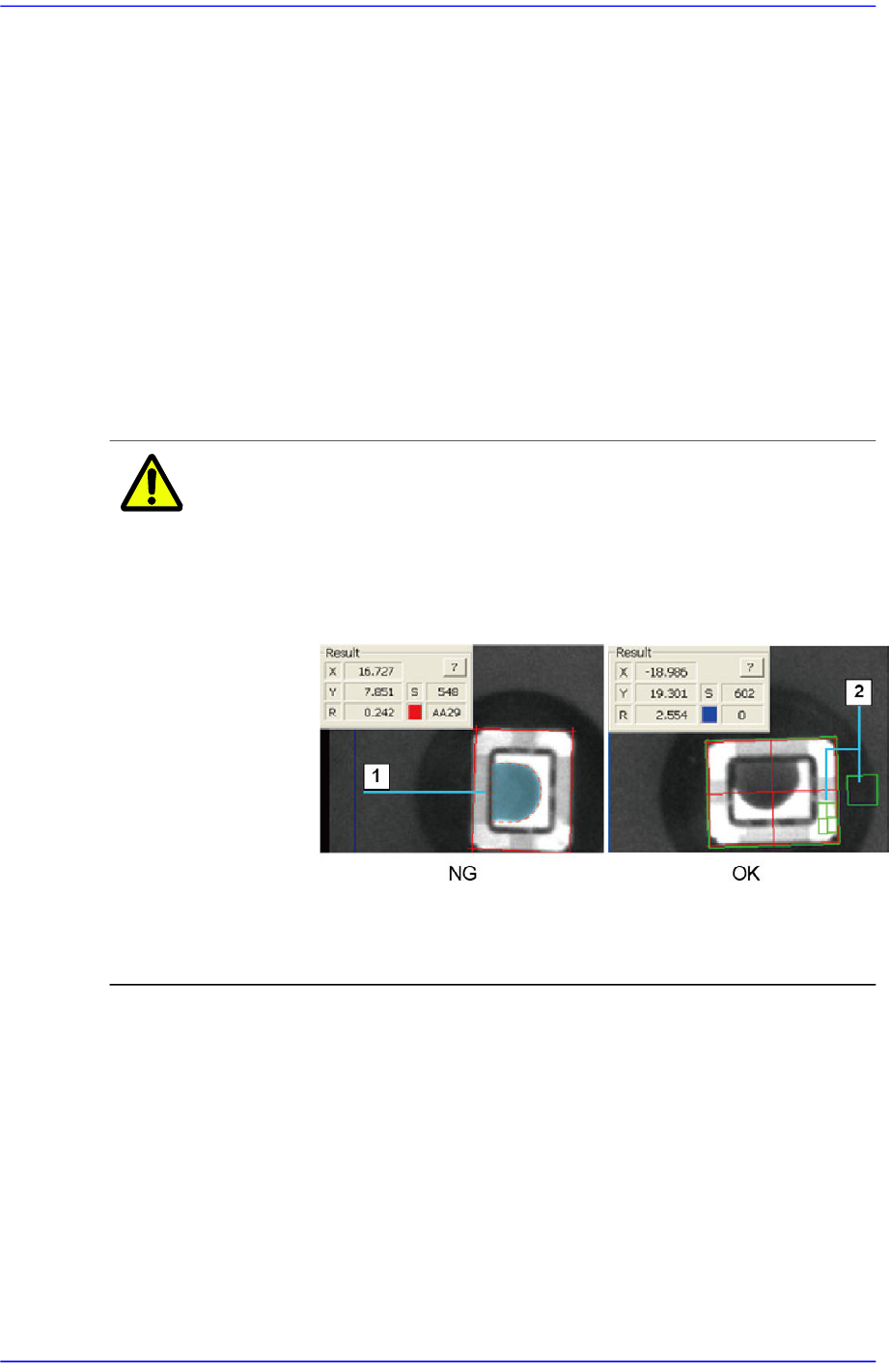
Caution In the case of a chip part showing a black circular shape as
shown in the following image, register the part using the
‘LED Flip check’ function.
Otherwise, even when the part has been picked up
normally, an error may occur as if it were not picked up.
1: The black circular shape is misrecognized as a nozzle.
2: The part is recognized normally using the LED Flip check function.
<Detail> button
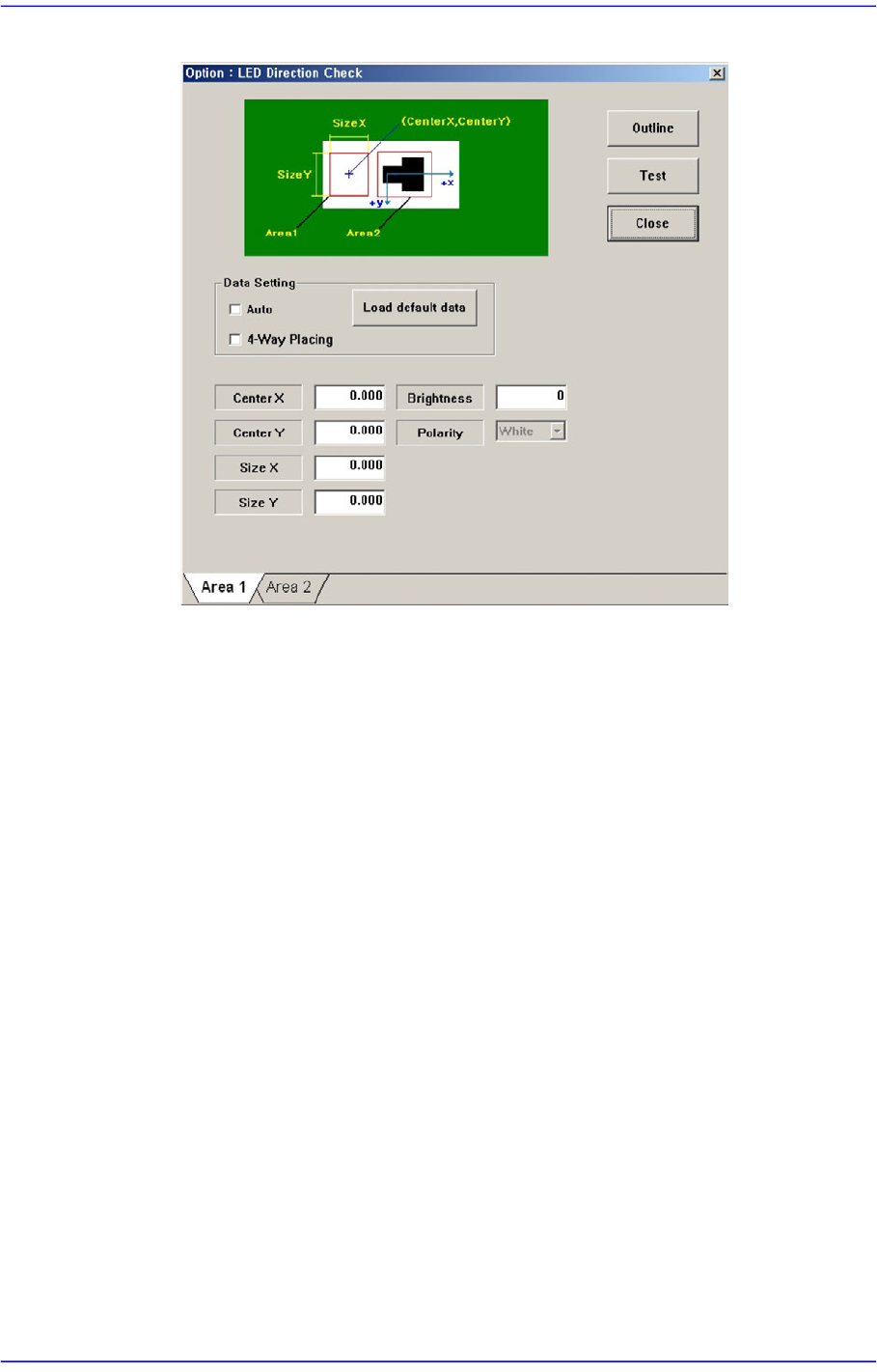
Executes the following dialog box used to set the details for the “Use LED flip
auto check”. This button is enabled only when the <Use LED flip auto check>
check box is selected.
7-43
Part Registration
Figure7.14 “LED direction check” check box
Set the White area of the LED in the ‘Area 1’ tab dialog box.
Center X
Refers to the coordinate in the X direction of the White area based on the
part center. (Refers to the figure in the dialog box)
Center Y
Refers to the coordinate in the Y direction of the White area based on the
part center. (Refers to the figure in the dialog box)
Size X
Size of the tetragonal area in the X direction (mm)
Size Y
Size of the tetragonal area in the Y direction (mm)
Brightness
Refers to the reference value of the White area. The White area with a
value less than the reference value can be considered normal. Generally, it
has a value of 200 and above.
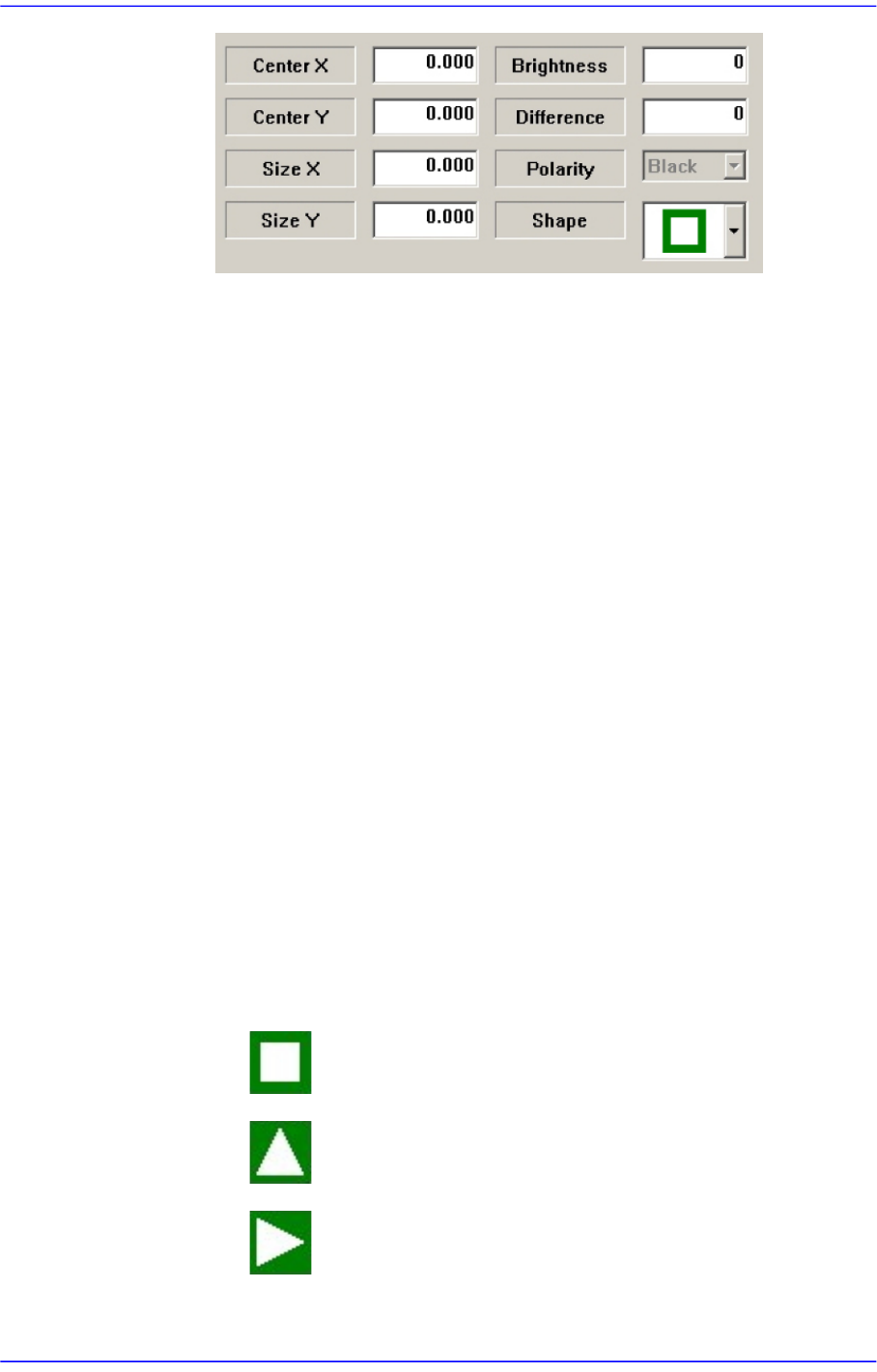
Set the Black area of the LED in the ‘Area 2’ tab dialog box.
7-44
Advanced Chip Shooter DECAN S2 Administrator’s Guide
Center X
Refers to the coordinate in the X direction of the Black area based on the
part center. (Refers to the figure in the dialog box)
Center Y
Refers to the coordinate in the Y direction of the Black area based on the
part center. (Refers to the figure in the dialog box)
Size X
Size of the tetragonal area in the X direction (mm)
Size Y
Size of the tetragonal area in the Y direction (mm)
Brightness
Refers to the reference value of the White area. The White area with a
value greater than the reference value can be considered normal.
Difference
Input the minimum difference in the brightness between <Area 1> and
<Area 2>. Generally, input 40.
Shape
Select a shape according to the mark or concavo-convex on the bottom surface
of the LED. If the concavo-convex shape is selected, the brightness of the
selected area as well as the direction of a protrusion are checked. This,
therefore, prevents the part from being placed upside down.
: There is no shape.
: Triangle mark in the 0° direction.
: Triangle mark in the 90° direction.