DECAN_S2_Admin(Eng_Ver4.5).pdf - 第530页
16-7 Diagnosis <Outer>: The range of the Outer l i ght level is 0~15. <Inner>: The r ange of the Inner light level is 0~15. <Close> button Closes the dialog b ox.
16-6
Advanced Chip Shooter DECAN S2 Administrator’s Guide
16.3. Light [F4]
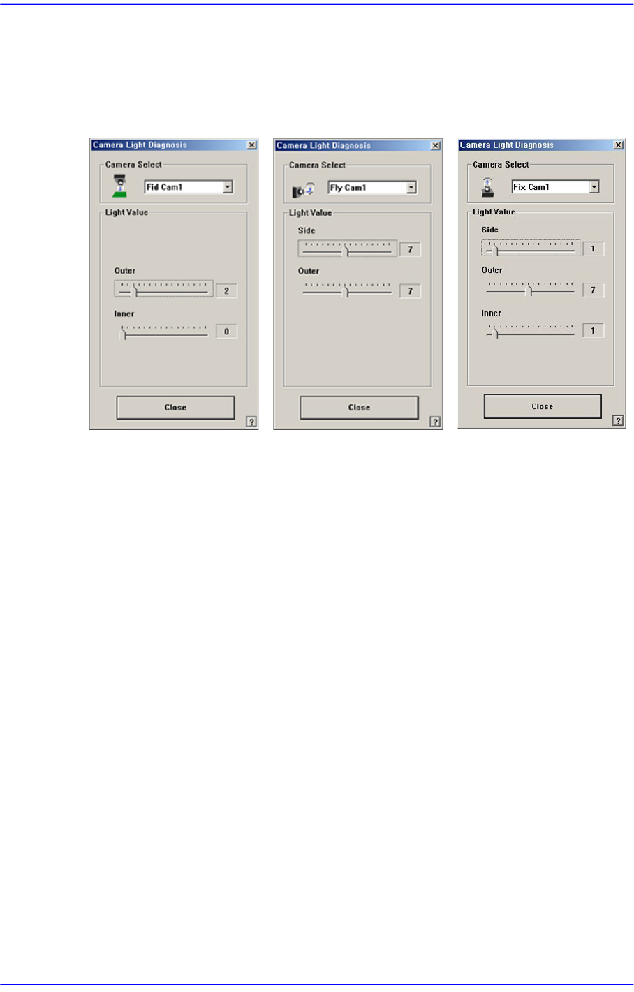
Checks the lighting devices installed on the fiducial camera, fly camera, and fix camera.
Figure16.6 “Camera Light Diagnosis “dialog box
<Camera Select> combo box
Select the camera on which the lighting device to be checked is installed.
Fid Cam2: Select the fiducial camera on the front gantry.
Fid Cam4: Select the fiducial camera on the rear gantry.
Head 1 ~ Head 20: Select #1 ~ #20 heads.
Fix Cam1: Select the fix camera.
<Light Value> group
Set the light value.
When the fiducial camera is selected, the range of light level that can be set is as
follows.
<Outer>: The range of the Outer light level is 0~15.
<Inner>: The range of the Inner light level is 0~15.
When the fly camera is selected, the range of light level that can be set is as follows.
<Side>: The range of the side light level is 0~15.
<Outer>: The range of the Outer light level is 0~15.
<Coaxial>: The range of the Coaxial light level is 0~15.
When the fix camera is selected, the range of light level that can be set is as follows.
<Side>: The range of the side light level is 0~15.

16-7
Diagnosis
<Outer>: The range of the Outer light level is 0~15.
<Inner>: The range of the Inner light level is 0~15.
<Close> button
Closes the dialog box.
16-8
Advanced Chip Shooter DECAN S2 Administrator’s Guide
16.4. Vacuum [F5]
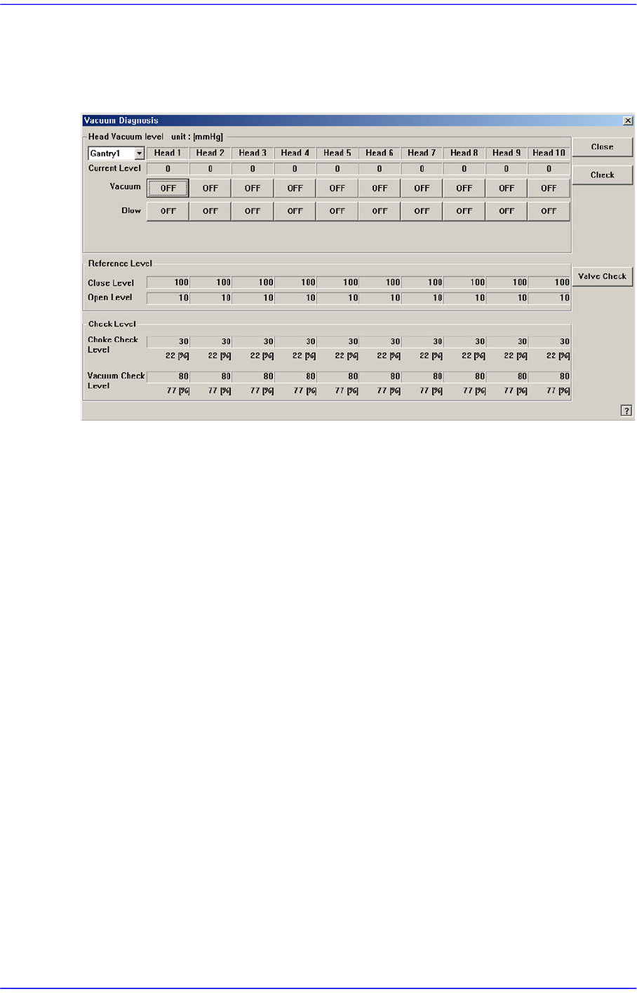
Checks the air pressure status of the head.
Figure16.7 “Vacuum Diagnosis” dialog box
<Head Vacuum level> group
Displays the vacuum level of each head and controls the vacuum generator.
<Gantry> combo box
Select the gantry for which the pneumatic pressure can be checked.
<Current Level>
Indicate the current pneumatic pressure of each head.
<Vacuum OFF> button
Pressing this button when “OFF” is indicated will supply constant pneumatic
pressure of 0.1Mpa inside the spindle and indicate “ON” on the button.
<Blow OFF> button
Pressing this button when “On” is indicated will shut off the pneumatic pressure
supplied to the spindle and indicate “OFF” on the button.
<Reference Level> group
When the vacuum level is used as a criteria for determining the component pick-up by
each head, displays the standard value.
<Close Level>
Indicate the pneumatic pressure of each head when the nozzle hole is plugged,
with the nozzle being inserted into the nozzle holder.
<Open Level>
Indicate the vacuum value of each head when the nozzle hole is opened, with the