DECAN_S2_Admin(Eng_Ver4.5).pdf - 第469页
15-18 Advanced Chip Shooter DECAN S2 Admi nistra t or’s Guide Set the data related to RS-232C c ommunication. <Ch annel> c om bo box Select the RS-232C communication channel. 2 channels are available for the mach…
15-17
System Setup
15.3.2. <Tray Feeder> Tab dialog
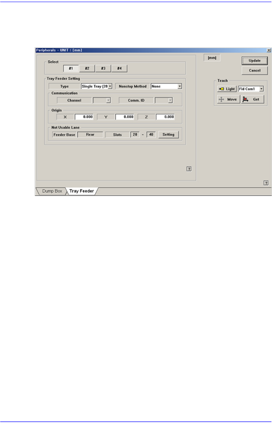
Sets the tray feeder related data. Selecting this button will display following dialog box.
Figure15.8 “Accessory” dialog box “Tray Feeder” Tab dialog
<Select> option button
Selects the tray feeder unit. Available tray feeder units are No. 1 to No.4 tray feeder
units.
That is, a total of 4 tray feeders can be installed. (Maximum 2 trays can be installed for
the type of trays that can communicate with the equipment.)
<Tray Feeder Setting> group
Selects the type of the set tray feeder unit. Available type is as follows.
<Type> combo box
Selects the type of the set tray feeder unit. Available type is as follows:
NONE: Means that no tray is installed.
Single Tray[39321]: Refers to the tray installed on the feeder base.
<Nonstop Method> combo box
Determines whether to use the non-stop function.
Note: The nonstop function is not used.
Master/Slave: One rack is used as master and another rack is used as slave.
Master/Master: One rack is used until the parts are exhausted, and then
another rack is used.
<Communication> group

15-18
Advanced Chip Shooter DECAN S2 Administrator’s Guide
Set the data related to RS-232C communication.
<Channel> combo box
Select the RS-232C communication channel. 2 channels are available for the
machine. Perform setup so that it may not be duplicated.
<Comm. ID> combo box
Select the communication ID. The used ID is 1 –3. Since only ID 1 is
supported, set the ID to ID 1.
<Origin> group
Setup origin of the selected ‘Tray Feeder Unit’. This origin is the offset value from
the origin of the equipment.
<Not Usable Lane> group
Sets the feeder base unit and slot occupied by the corresponding tray when using the
selected tray feeder unit.
<Feeder Base> combo box
Selects the feeder base. The selectable feeder base is front (Front Feeder Base or
Rear Feeder Base).
<Lane> edit box
Sets the slot the feeder base.
<Update> button
Transmits the change data to the equipment and closes the dialog box.
<Cancel> button
Ignores the change data and closes the dialog box.
15-19
System Setup
15.4. Light [F8]
Calibrate the brightness of the light for the camera. In order to perform this calibration,
insert a nozzle for camera test (LightFix) into the ANC.
Caution Since the nozzle for the SM32x,SM411, SM421 model is
not compatible to the one for the light mapping used for the
SM32x,SM411, SM421 model, do not use it for this
machine.
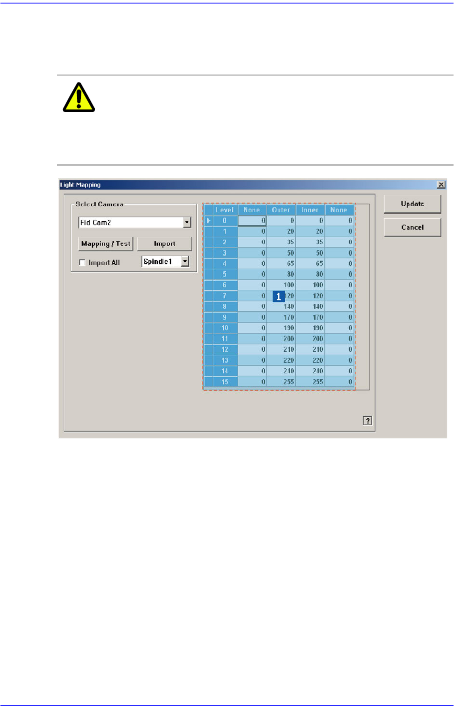
1: Light Level group
<Select Camera> combo box
Selection Control
Select the camera to perform light mapping.
Light Level group
Sets the brightness by light level.
<Level> column
Displays 16 steps of lighting.
<Side> / <Inner> / <Outer>/ <Coaxial> column
For the Fid Camera: Input the side illumination value within the range of 256
values.
For the Fly Camera: Input the side illumination value within the range of 256