OM-1012-001.pdf - 第104页
5.2 Program Change Tg0869-PM-OM 5.2.2.5 Partition Plate Installation Procedure in Even Steps (1) Pull the grip of the magazine door fixture down in the direction of Arrow A to unlatch the magazine door . (Figs. A37 and A…
5.2 Program Change
Tg0869-PM-OM
Left Side
Right Side
Step No.
Bolt
Partition Plate
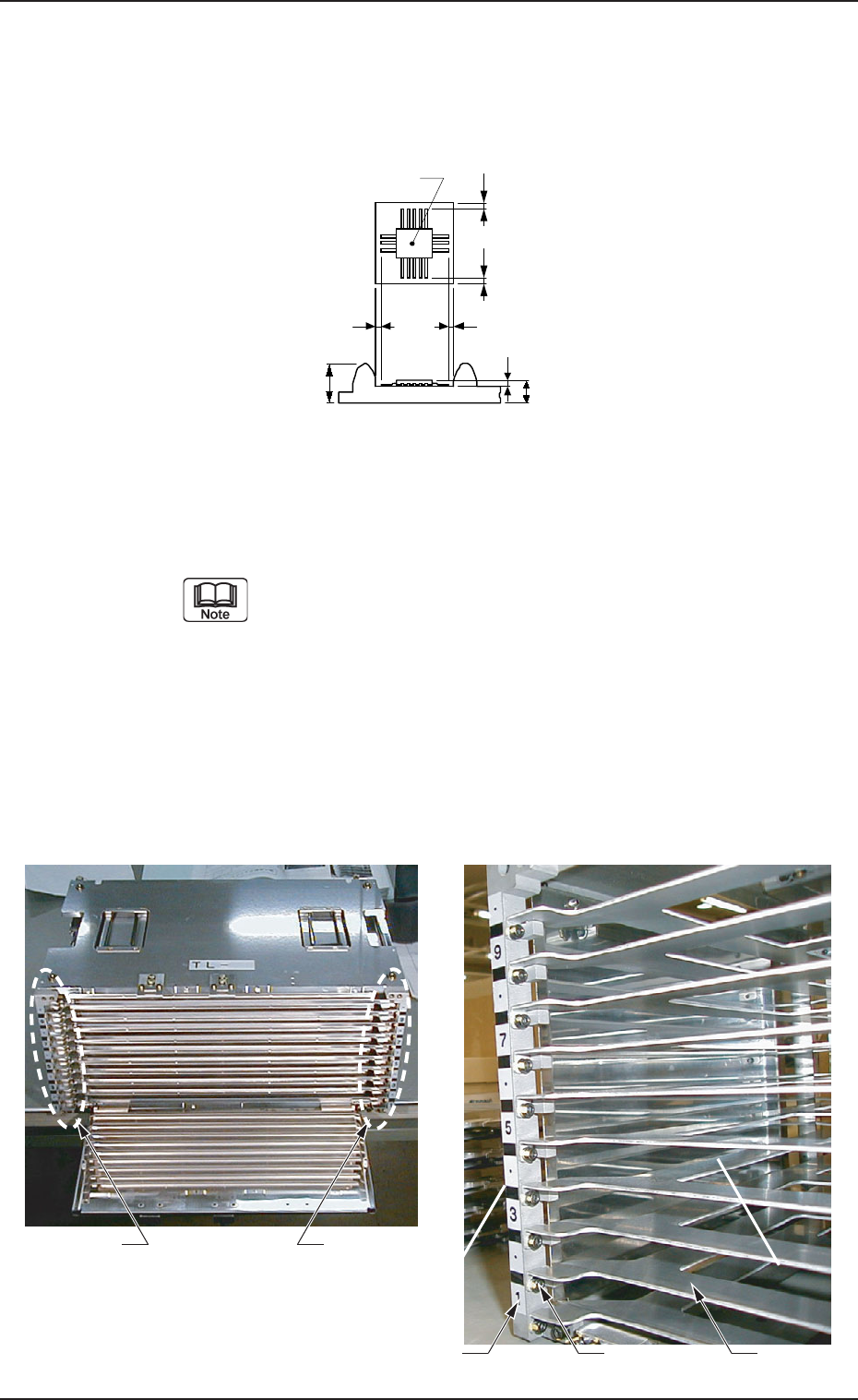
5.2.2.4 Partition Plate Removal Procedure in Even Steps
• When a component of 11.5 mm or more in height is placed on the tray t1or
t2, the partition plate (even steps) should be detached to avoid interference
of the partition plate with the component.
(1) Pull the grip of the magazine door fixture down in the direction of
Arrow A to unlatch the magazine door.
(Figs. A37 and A38 Arrow A)
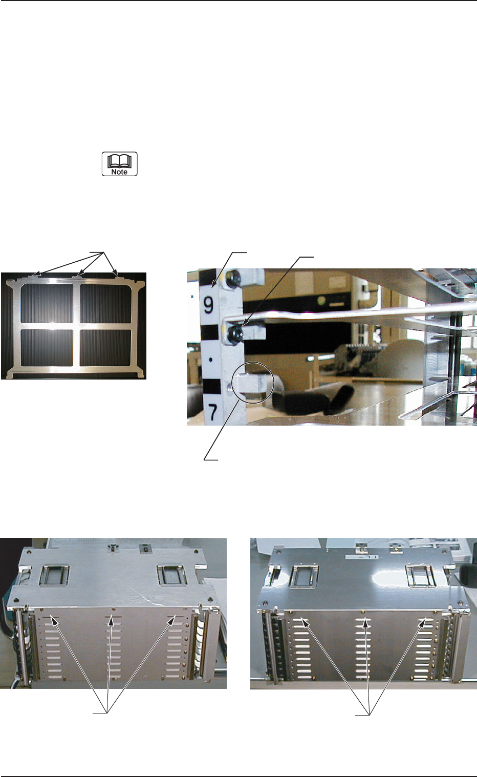
(2) Open the magazine door. (Fig. A39 Arrow B)
(3) Remove the bolts fixing the partition plate and remove the plate.
(a) When the partition plate is removed, confirm
the step No. and remove the partition plate only at
the even steps. If the partition plate at the odd
stage is removed and the pallet is set there, the
pallet can’t be drawn out from the magazine during
peration.
(b) The partition plate and bolts, which have been
removed will be used when the partition plate is
installed again. Set aside with care. Also, handle
the partition plate carefully because it is easily
deformed.
Fig. A46
Fig. A47 Partition Plate Anchor Bolt Position
SS
S
t
Component
S
t
1
t
2
0305-001 Chapter 1 2-24
5.2 Program Change
Tg0869-PM-OM
5.2.2.5 Partition Plate Installation Procedure in Even Steps
(1) Pull the grip of the magazine door fixture down in the direction of Arrow
A to unlatch the magazine door. (Figs. A37 and A38 Arrow A)
(2) Open the magazine door. (Fig. A39 Arrow B)
(3) Place the partition plate on the fixing block (refer to Fig. A49) and insert
it in the magazine so that the projections of the partition plate come out
from the openings at the rear wall of the magazine. (Refer to Figs. A50
and A51).
When the partition plate is being set in the magazine, note the
direction of the partition plate. Handle the magazine door and
partition plate carefully because they are easily deformed. If
the magazine door or partition plate is deformed, an error or
machine breakdown might be caused.
Fig. A50
Fig. A51
0305-001 Chapter 1 2-25
Fig. A49 Fixing Block (On the Left) Positions
(Same for on the Right)
Step No.
Fixed block with the partition plate removed
Bolt
Fig. A48 Partition Plate
Protrusions
Opening where the partition
plate protrusions are inserted
Condition showing protrusions
coming out from the openings
5.2 Program Change
Tg0869-PM-OM
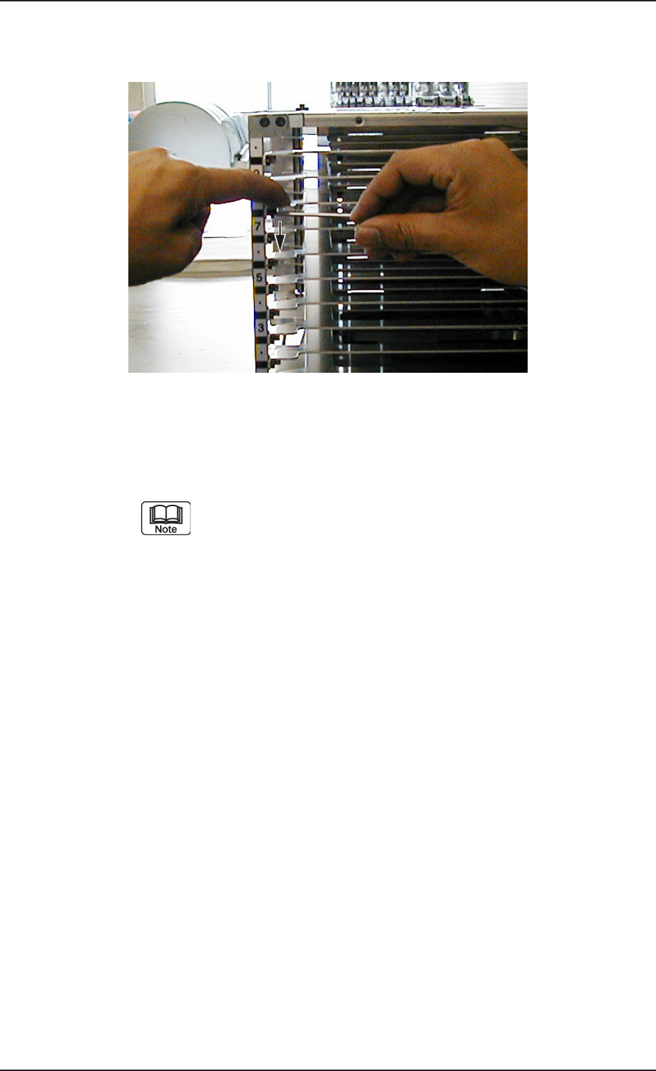
Fig. A52 Fix the partition plate. (Same for right and left.)
(5) Check visually that the partition plate is correctly placed on the block
and that the partition plate shows no warpage or deformation.
If there is any nonconformity, repeat the attachment procedure
from the beginning because it might cause machine breakdown.
(4) Press the partition plate with the fingers so that it does not rise, as shown
in Fig. A52, and fix it with bolts (left and right, two locations)
0305-001 Chapter 1 2-26