OM-1012-001.pdf - 第97页
5.2 Program Change Tg0869-PM-OM (5) Pull out the pins, etc., which were inserted in Step (3). The tray is suppressed in the Y direction. 5.2.1.3 T ray Detachment from Pallet (1) Push the lever of the tray fixing metal an…
5.2 Program Change
Tg0869-PM-OM
(3) While keeping the lever at the standard position, insert the pins, etc., into
the φ 3.1 holes to temporarily lock the lever such that the lever does not
return.
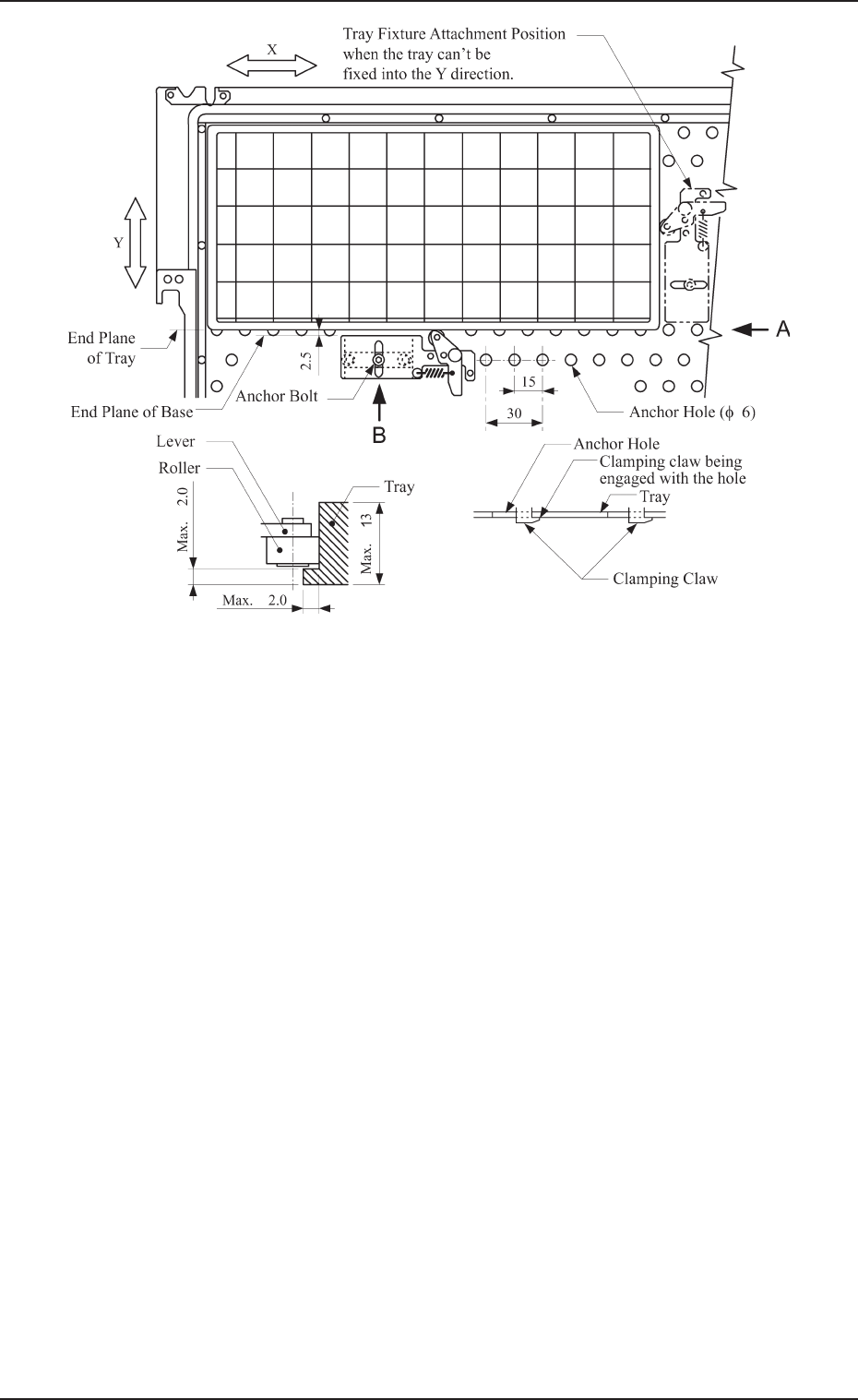
(4) Fasten the tray fixing metal to the pallet along the longer side of the tray.
• Positioning
The roller of the tray fixing metal should be located at the position
close to the center of the longer side of the tray and the clearance be-
tween the end planes of the base and the tray should become approxi-
mately 2.5 mm.
Note: When a tray fixing metal cannot be attached along the longer
side of the tray, it should be mounted close to the center of the
shorter side.
• Locking
Tighten the anchor bolt while the clamping claw of the tray fixing metal
is engaged with the anchor hole on the pallet (View B in Fig. A32).
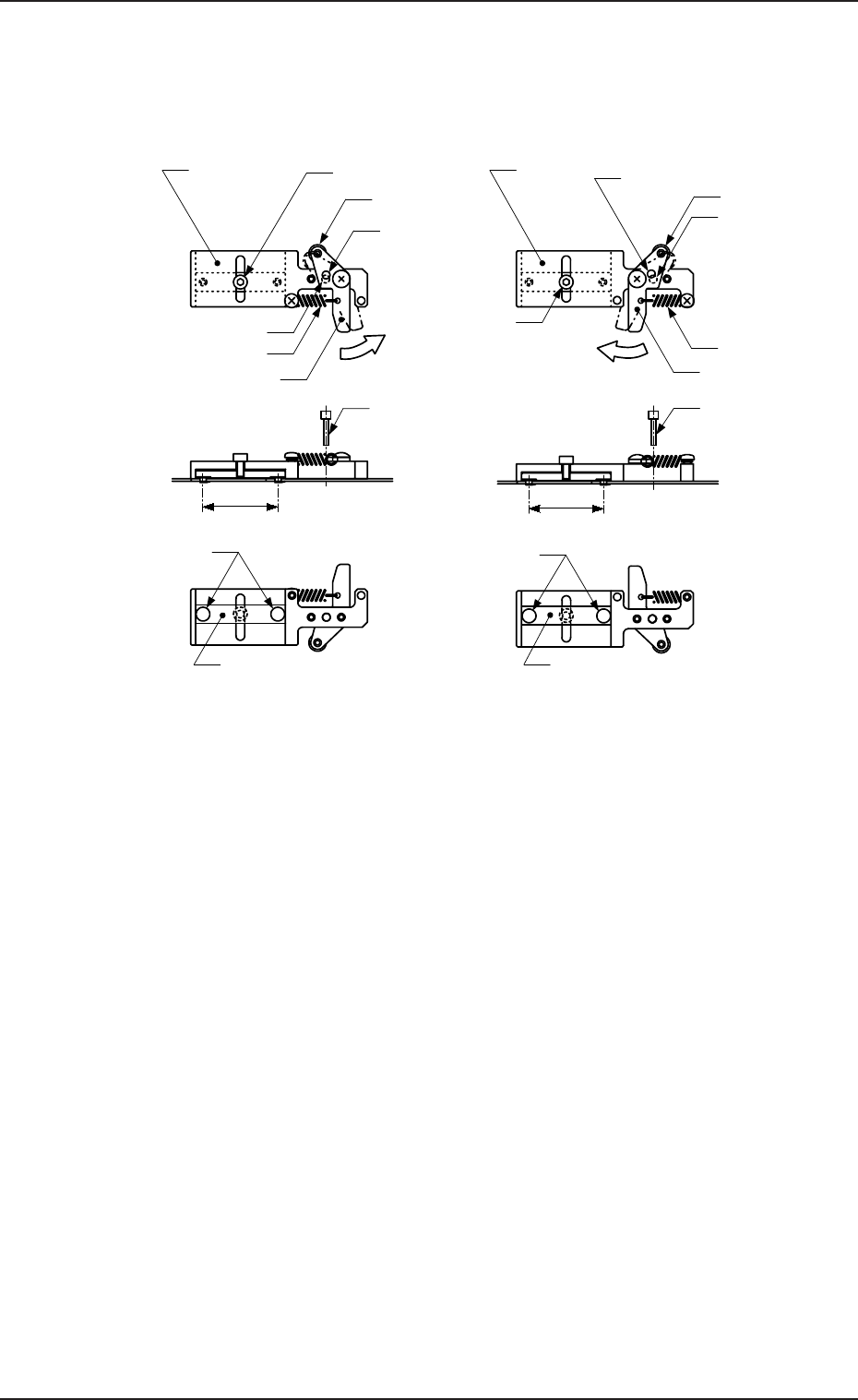
Fig. A31 Tray Fixing Metals
(2) Push the lever of the tray fixing metal in the arrow direction and hold it at
the position where the φ 3.1 hole of the lever aligns with the φ 3.1 hole of
the base.
This position is called “Standard Position”.
Roller
Anchor Bolt
Lever
Spring
Roller
Anchor Bolt
Base
φ
3.1 Hole
(For Lever)
Lever
Spring
Push the lever.
Push the lever.
φ
3.1 Hole
(For Base)
Base
φ
3.1 Hole
(For Lever)
φ
3.1 Hole
(For Base)
MF-5050L (For MG-5050L)
Clamping Claw
(
φ
5.5)
Clamp Block
MF-5050R (For MG-5050R)
Clamp Block
Clamping Claw
(
φ
5.5)
30
30
Pin, etc. (
φ
3
)
Pin, etc. (
φ
3)
Unit: mm
0305-001 Chapter 1 2-17
5.2 Program Change
Tg0869-PM-OM
(5) Pull out the pins, etc., which were inserted in Step (3).
The tray is suppressed in the Y direction.
5.2.1.3 Tray Detachment from Pallet
(1) Push the lever of the tray fixing metal and hold it at the position where
the roller of the metal has separated from the tray.
(2) Detach the tray from the pallet.
View A View B
Fig. A32 Location of Fixing Metals for TL (Same for TR)
0305-001 Chapter 1 2-18
5.2 Program Change
Tg0869-PM-OM0305-001 Chapter 1 2-19
5.2.2 Preparation of Magazine
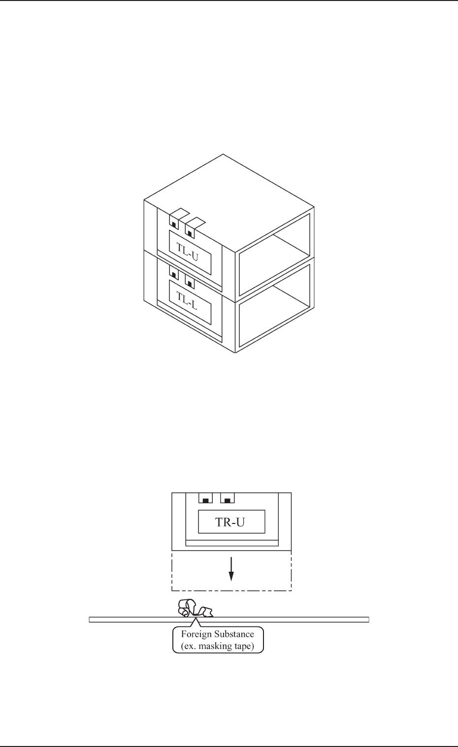
5.2.2.1 Precautions in Magazine Handling
• Do not pile up magazines removed from the unit. Do not put anything
on the upper surface of the magazine. If the magazine is deformed it
can cause such abnormality as machine breakdown when the magazine
is set on the tray feeder.
• When the magazine is put on the desk or floor, ensure there is no dust
or foreign substance on the magazine’s base. If the magazine is placed
as shown in Fig. A33 and set in the unit with dust or other foreign
substance on the magazine base it can cause breakdown, because the
machine is operated with the magazine inclined.
Fig. A33
Fig. A34