OM-1012-001.pdf - 第258页
Chapter 5 2-21 Tg0869-PM-OM 0305-001-(M807WTR--0006) 3.6 SDS OUT 1 3.6 SDS OUT 1 Note : It shows the diagram within dotted lines is within the relay PCB.
Chapter 5 2-20 Tg0869-PM-OM
0305-001-(M807WTR--0005)
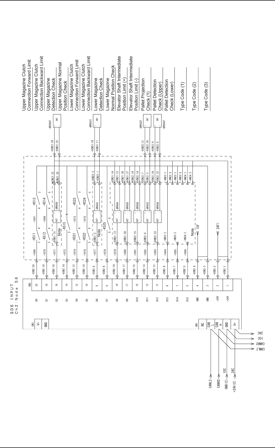
3.5 SDS IN 2
3.5 SDS IN 2
Note : It shows the diagram within dotted lines is within the
relay PCB.
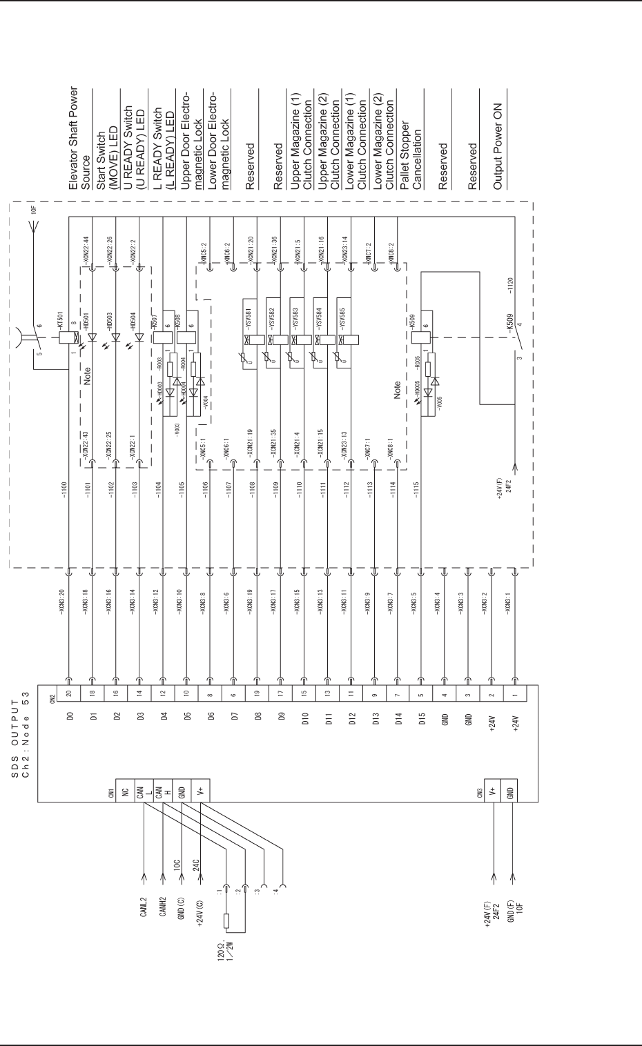
Chapter 5 2-21 Tg0869-PM-OM
0305-001-(M807WTR--0006)
3.6 SDS OUT 1
3.6 SDS OUT 1
Note : It shows the diagram within dotted lines is within the
relay PCB.
Chapter 5 2-22 Tg0869-PM-OM0305-001-(M807WTR--0007)
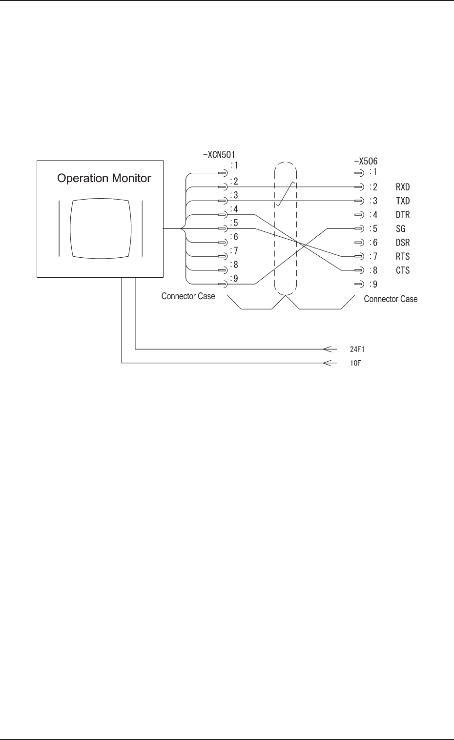
3.7 Operation Monitor Circuit Diagram
3.7 Operation Monitor Circuit Diagram