OM-1012-001.pdf - 第184页
0305-001 Chapter 3 2-23 Tg0869-PM-OM 4. T roubleshooting after Error Message 12 02 01 TV2-AXIS TIMING PREVIOUS T ASK W AS NOT COMPLETED. UNABLE TO CONTINUE. 12 03 01 TV2-AXIS DA T A T ARGET LOCA TION V ALUE IS OUT OF RAN…
0305-001 Chapter 3 2-22 Tg0869-PM-OM
4. Troubleshooting after Error Message
12 01 0A TV2-AXIS ORIGIN TRAVERSE AXIS (+) LIMIT [BPH256] SENSOR MAY
BE DEFECTIVE.
12 01 0B TV2-AXIS ORIGIN TRAVERSE 2 LEVER A ORIGIN [BPH264] NOT DE-
TECTED.
Error Code Display A Display B
(Cause 1) This is the device’s self-diagnostic message.
(Reset Procedure in the case of Cause 1)
Reset Procedure
(1) Press the [CLEAR ALARM] key to stop the buzzer sound.
(2) Press the [RESET] button to cancel the error mode.
(3) Press the [ZERO] button to return all axes to their original positions. Continue the produc-
tion according to the “WARM Start Operation Procedure”.
(4) If the device can’t be reset after the above procedure, contact our service personnel.
12 01 0C TV2-AXIS ORIGIN TRAVERSE 2 LEVER B ORIGIN [BPH265] NOT DE-
TECTED.
(Cause 1) This is the device’s self-diagnostic message.
(Reset Procedure in the case of Cause 1)
Reset Procedure
(1) Press the [CLEAR ALARM] key to stop the buzzer sound.
(2) Press the [RESET] button to cancel the error mode.
(3) Press the [ZERO] button to return all axes to their original positions. Continue the produc-
tion according to the “WARM Start Operation Procedure”.
(4) If the device can’t be reset after the above procedure, contact our service personnel.
12 01 0D TV2-AXIS ORIGIN TRAVERSE 2 CLAMP AREA CHECK A [BPH264] NOT
DETECTED.
12 01 0E TV2-AXIS ORIGIN TRAVERSE 2 CLAMP AREA CHECK B [BPH254] NOT
DETECTED.
(Cause 1) This is the device’s self-diagnostic message.
(Reset Procedure in the case of Cause 1)
Reset Procedure
(1) Press the [CLEAR ALARM] key to stop the buzzer sound.
(2) Press the [RESET] button to cancel the error mode.
(3) Press the [ZERO] button to return all axes to their original positions. Continue the produc-
tion according to the “WARM Start Operation Procedure”.
(4) If the device can’t be reset after the above procedure, contact our service personnel.
0305-001 Chapter 3 2-23 Tg0869-PM-OM
4. Troubleshooting after Error Message
12 02 01 TV2-AXIS TIMING PREVIOUS TASK WAS NOT COMPLETED. UNABLE
TO CONTINUE.
12 03 01 TV2-AXIS DATA TARGET LOCATION VALUE IS OUT OF RANGE.
Error Code Display A Display B
(Cause 1) This is the device’s self-diagnostic message.
(Reset Procedure in the case of Cause 1)
Reset Procedure
(1) Press the [CLEAR ALARM] key to stop the buzzer sound.
(2) Press the [RESET] button to cancel the error mode.
(3) Press the [ZERO] button to return all axes to their original positions. Continue the produc-
tion according to the “WARM Start Operation Procedure”.
(4) If the device can’t be reset after the above procedure, contact our service personnel.
12 04 01 TV2-AXIS LIMIT LIMIT ERROR (+) IS DETECTED.;BPH256
12 04 02 TV2-AXIS LIMIT LIMIT ERROR (-) IS DETECTED.;BPH257
(Cause 1) It may run away due to noise or overcurrent.
(Cause 2) The sensor may be defective.
(Reset Procedure in the case of Causes 1 and 2)
Reset Procedure
(1) Press the [CLEAR ALARM] key and the buzzer stops sounding.
(2) Press the [ZERO] button to return all the axes to their original positions.
(3) Re-start.
(4) If the device can’t be re-started, contact our service personnel.
0305-001 Chapter 3 2-24 Tg0869-PM-OM
4. Troubleshooting after Error Message
12 05 TV2-AXIS INTERLOCK Reserved
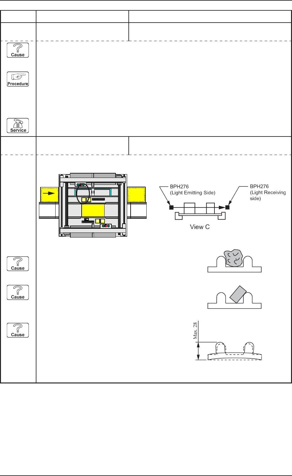
12 05 02 TV2-AXIS INTERLOCK TRAVERSE 1 PATH LINE [BPH276] DETECTED.
Error Code Display A Display B
(Cause 1) This is the device’s self-diagnostic message.
(Reset Procedure in the case of Cause 1)
Reset Procedure
(1) Press the [CLEAR ALARM] key to stop the buzzer sound.
(2) Press the [RESET] button to cancel the error mode.
(3) Press the [ZERO] button to return all axes to their original positions. Continue the produc-
tion according to the “WARM Start Operation Procedure”.
(4) If the device can’t be reset after the above procedure, contact our service personnel.
PCB
Beam A Side
Beam B Side
C
(Cause 1) Is there any foreign substance on the tray ?
Check the tall component on the pallet.
(Cause 2) Is the component not properly in the tray ?
A component which was not picked up might be
sticking out from the tray.
(Cause 3) Is the height of the tray close to the specified
maximum limit ?
(NEXT PAGE)