OM-1012-001.pdf - 第108页
5.2 Program Change Tg0869-PM-OM (6) Hold the magazine handle (Refer to Fig. A57) and set the magazine care- fully on the magazine mounting section: then press the magazine against the rear stopper . Confirm that the maga…
5.2 Program Change
Tg0869-PM-OM
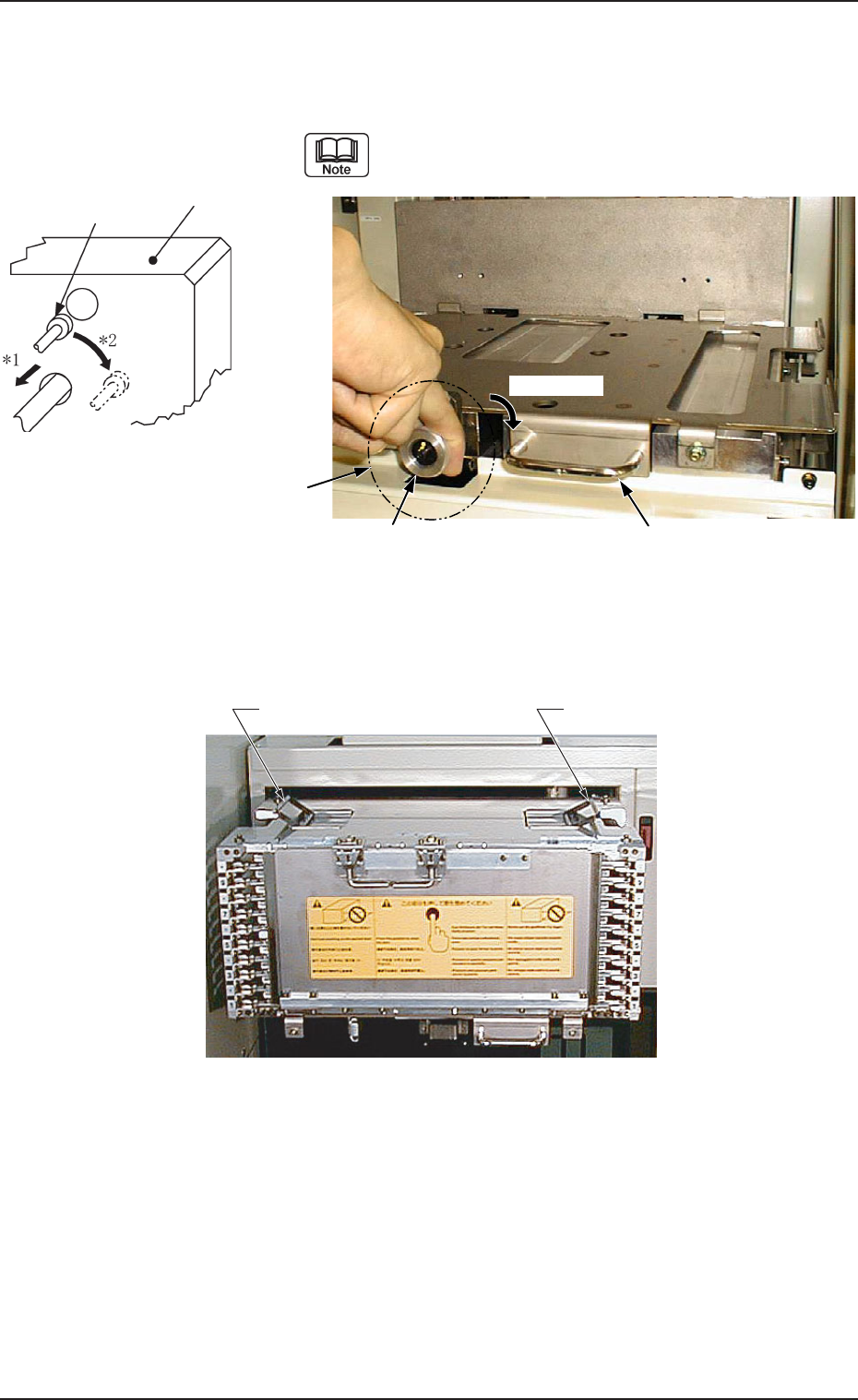
(4) Put the knob of the magazine stopper between fingers as
shown in Fig. A56 and turn it clockwise by approx. 90°
‹while pulling it forward.
(See Arrows *1 and *2 in Fig. A55.)
Pulling Force of Magazine Stopper
39.2 N to 49.0 N (4 to 5 kgf)
Fig. A55
Fig. A57 Grips of Magazine “MG-5050L” (Same to “MG-5050R”)
(5) Hold the handle of the magazine base and pull it forward until it stops.
Locking Pin
Block
Fig. A56 Magazine Base
Knob Handle
Approx. 90°
Magazine Stopper
0305-001 Chapter 1 2-28
Grip of Magazine
Grip of Magazine
5.2 Program Change
Tg0869-PM-OM
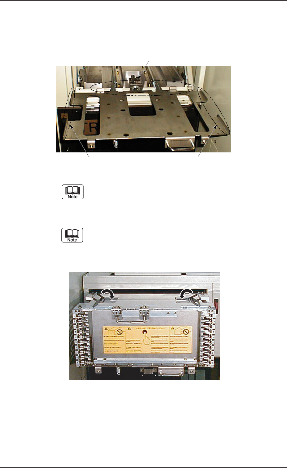
(6) Hold the magazine handle (Refer to Fig. A57) and set the magazine care-
fully on the magazine mounting section: then press the magazine against
the rear stopper.
Confirm that the magazine is set in place along the side and rear stoppers
and is not tilted.
Fig. A59 The status before folding the grip of the magazine.
“MG-5050L” (Same to “MG-5050R”)
Fig. A58 Magazine Base (Slid Out)
There are two types of magazines - “MG-5050L” for “FP-5022L”
and “MG-5050R” for “FP-5022R”. Do not make a mistake of
wrong selection. Otherwise, an error will occur.
(7) Fold down (close) the grips of the magazine.
When the magazine is pushed inward with the grips kept open,
the grips will be caught by the multi-layer tray feeder, blocking
the way to the rear end.
0305-001 Chapter 1 2-29
Side Stopper Side Stopper
Rear Stopper
5.2 Program Change
Tg0869-PM-OM
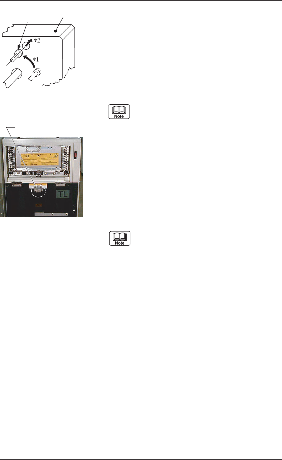
(8) Hold the handle of the magazine base and slowly push
the base until it touches the rear end.
(9) Follow the reverse procedure of Step (4) to push the
magazine stopper back to the specified position.
(See Arrows *1 and *2 in Fig. A60.)
When the magazine is set correctly at the specified po-
sition, it is locked by the magazine stoppers.
(10) Close the door (the upper or the lower door) of the
magazine-loaded side.
The doors are provided with unlocked maga-
zine prevention metal fixtures to check
whether the magazines are securely locked.
The doors may be closed when they are de-
formed and the magazine stoppers are not lo-
cated at their specified positions, depending
upon the environmental condition (high am-
bient temperature, etc.).
When the main machine is operated with the
magazine unlocked, the magazine starts mov-
ing in the elevator and may damage the feeder.
(11) Press the [U READY] or the [L READY] button on the
magazine-loaded side.
The LED of the pressed button illuminates.
The machine stores the matrix position of the
last component ID (component used last) in
memory after the current program is changed
to another one.
When the tray in the middle of process is re-
plenished with components for program
change operations, some previous components
may remain in the tray. Therefore, it is required
to change the matrix.
Refer to “2. Component Replenishment of
Section 3 in Chapter 1 ”, “4. Matrix Change
Operations of Section 3 in Chapter 1”, and
“11.1.3 Tray Chuck Matrix Change Operations
of Section 2 in Chapter 1” for details.
Fig. A61
Fig. A60
Locking Pin
Block
0305-001 Chapter 1 2-30
Unlocked Magazine
Prevention Metal Fixture