OM-1012-001.pdf - 第12页
0305-001 11 Tg0869-PM-OM About Precaution Labels About Safety Precaution Labels • The following warning signs are classified into three categories according to the degree of danger . Please fully understand the meaning o…

Contents
Page
0305-001 10 Tg0869-PM-OM
Chapter 5 Materials .............................................. Chapter 5 1
Section 1 Air Piping Diagram ................................................ Chapter 5 1- 1
1. Air Piping Diagram (FP-5022L, FP-5022R) ................... Chapter 5 1- 2
Section 2 Electrical Circuit Diagrams.................................... Chapter 5 2- 1
1. Electrical and Electronic Symbols ................................. Chapter 5 2- 2
2. Electrical Circuit Diagrams (FP-5022L) ......................... Chapter 5 2- 9
2.1 Elevator Circuit Diagrams ........................................ Chapter 5 2- 9
2.2 Power Supply Circuit Diagram 1 ............................. Chapter 5 2-10
2.3 Power Supply Circuit Diagram 2 ............................. Chapter 5 2- 11
2.4 SDS IN 1 .................................................................. Chapter 5 2-12
2.5 SDS IN 2 .................................................................. Chapter 5 2-13
2.6 SDS OUT 1 .............................................................. Chapter 5 2-14
2.7 Operation Monitor Circuit Diagram .......................... Chapter 5 2-15
3. Electrical Circuit Diagrams (FP-5022R) ........................ Chapter 5 2-16
3.1 Elevator Circuit Diagram ......................................... Chapter 5 2-16
3.2 Power Supply Circuit Diagram 1 ............................. Chapter 5 2-17
3.3 Power Supply Circuit Diagram 2 ............................. Chapter 5 2-18
3.4 SDS IN 1 .................................................................. Chapter 5 2-19
3.5 SDS IN 2 .................................................................. Chapter 5 2-20
3.6 SDS OUT 1 .............................................................. Chapter 5 2-21
3.7 Operation Monitor Circuit Diagram .......................... Chapter 5 2-22
Section 3 Location of Sensors, Switches, and Loads ........... Chapter 5 3- 1
1. Location of Sensors, Switches, and Loads (FP-5022L) ........ Chapter 5 3- 2
2. Location of Sensors, Switches, and Loads (FP-5022R) ....... Chapter 5 3- 3
Section 4 Parts Location ....................................................... Chapter 5 4- 1
1. Parts Location (FP-5022L) ............................................ Chapter 5 4- 2
1.1 Whole View Layout .................................................. Chapter 5 4- 2
1.2 Power Source Section Layout ................................. Chapter 5 4- 3
1.3 Relay PCB Layout ................................................... Chapter 5 4- 4
1.4 Operation Panel Layout ........................................... Chapter 5 4- 5
2. Parts Location (FP-5022R) ........................................... Chapter 5 4- 6
2.1 Whole View Layout .................................................. Chapter 5 4- 6
2.2 Power Supply Section Layout ................................. Chapter 5 4- 7
2.3 Relay PCB Layout ................................................... Chapter 5 4- 8
2.4 Operation Panel Layout ........................................... Chapter 5 4- 9
0305-001 11 Tg0869-PM-OM
About Precaution Labels
About Safety Precaution Labels
• The following warning signs are classified into three categories
according to the degree of danger.
Please fully understand the meaning of each sign for safety pre-
cautions.
• Identifying Alert Icons
: This symbol mark represents danger or prompts warning.
: This symbol mark represents prohibited operations.
: This symbol mark represents forced operations or instructions.
This indicates a potentially hazardous situation
which, if not avoided, may result in injury or physi-
cal damage.
CAUTION
DANGER
This indicates an imminently hazardous situation
which, if not avoided, will result in death or seri-
ous injury.
This indicates a potentially hazardous situation
which, if not avoided, could result in death or seri-
ous injury.
WARNING
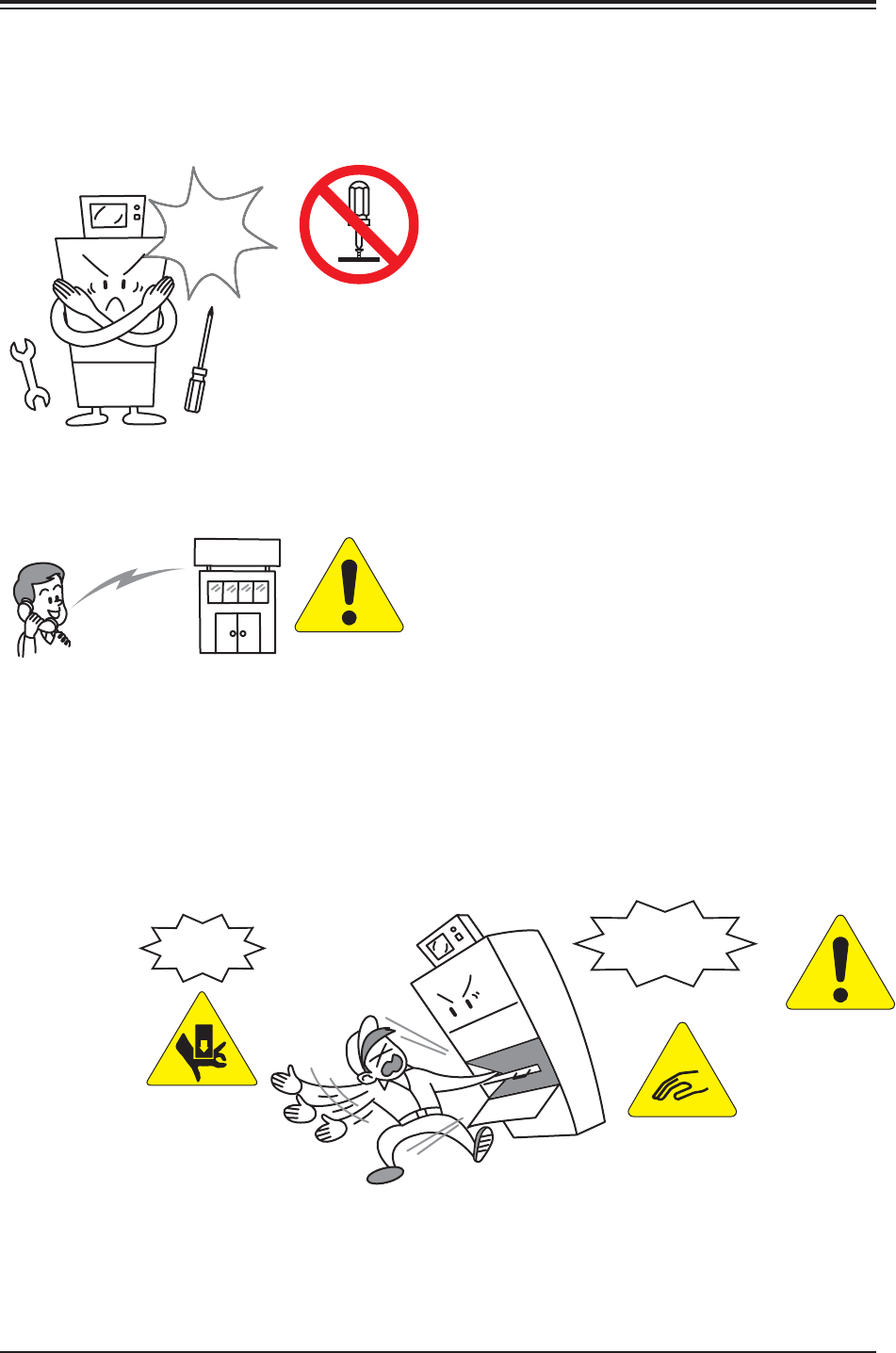
Checking Item
• Never modify any part of the device's body,
control system, safety door or emergency
stop switch.
We are not liable for damage resulting from
any modification made without our permis-
sion.
Please check the following items before use.
1. Modification Prohibition
• For specification changes, consult our mar-
keting deparment or sales agency.
0305-001 12
Tg0869-PM-OM
••
••
• Dangers resulting from Modification
(1) Safety Level Lowering
Contact
Agency
Example: Abnormalities caused by Noise/Defeating of Interlocking, etc.
Malfunction
Modification Prohibition
No
Injury
Modification
Prohibition
WARNING
CAUTION