OM-1012-001.pdf - 第249页
Chapter 5 2-12 Tg0869-PM-OM 0305-001-(M807WTL--0004) 2.4 SDS IN 1 2.4 SDS IN 1 Note : It shows the diagram within dotted lines is within the relay PCB.
Chapter 5 2-11 Tg0869-PM-OM0305-001-(M807WTL--0003)
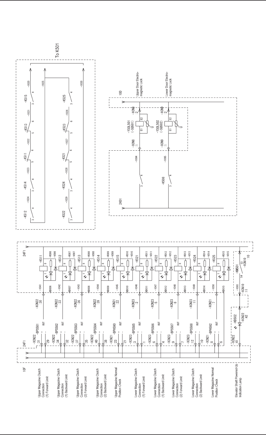
2.3 Power Supply Circuit Diagram 2
2.3 Power Supply Circuit Diagram 2
Note:It shows the diagram within dotted lines is within the relay PCB.
Chapter 5 2-12 Tg0869-PM-OM0305-001-(M807WTL--0004)
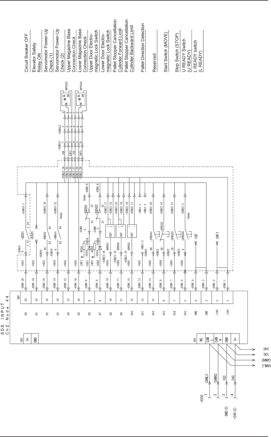
2.4 SDS IN 1
2.4 SDS IN 1
Note : It shows the diagram within dotted lines is within the relay PCB.
Chapter 5 2-13 Tg0869-PM-OM0305-001-(M807WTL--0005)
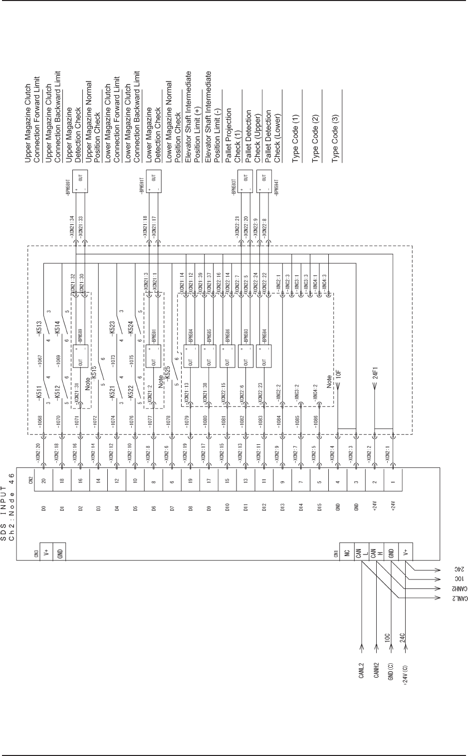
2.5 SDS IN 2
2.5 SDS IN 2
Note : It shows the diagram within dotted lines is within the
relay PCB.