OM-1012-001.pdf - 第89页
5.1.2.2 T ray Steps Information Refer to “2.5.4 T ray Step Information (Option) of Section 2 in V olume 2” and “4.5.3 Editing of T ray Steps Information Data (Option) of Section 2 in V ol- ume 2” in the main machine inst…
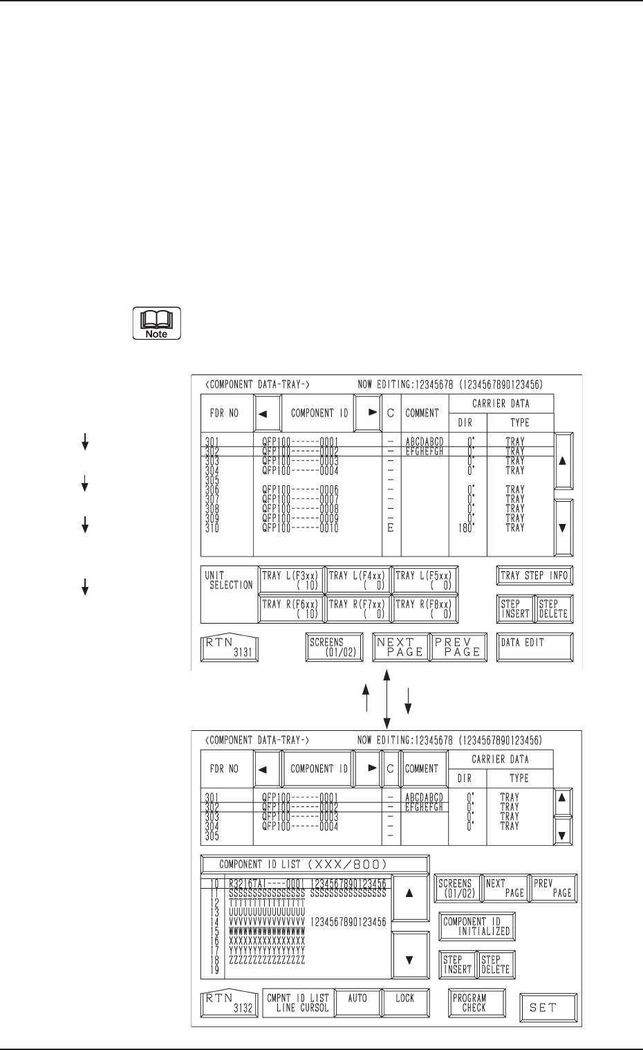
Fig. A18
Fig. A17
5.1.2 Component Data
5.1.2.1 Component Data
Refer to “2.5.3 Tray Feeders (Option) of Section 2 in Volume 2” and “4.5.2
Editing of Tray Component Data (Option) of Section 2 in Volume 2” in the
main machine instruction manual for details.
Data can be edited on the main machine side.
(1) Press the [TRAY L (F301-F599)] or the [TRAY R (F601-F899)] key at
the “PATTERN PROGRAM EDIT” display. The display (Fig. A17) ap-
pears on the screen.
(2) Press the [DATA EDIT] key.
The display (Fig. A18) appears on the screen.
(3) Component IDs are allocated to feeder Nos. (FDR No.).
The component data can be edited only with the main machine in
the “STOP” or “PAUSE” mode when the multi-layer tray feeder
is included in the production model.
Hierarchical Sequence
(Display)
“MAIN MENU”
“DATA EDIT”
“PATTERN PROGRAM”
“PATTERN PROGRAM
EDIT”
“COMPONENT DATA
-TRAY-”
5.1 Preparation (Outline) for Pattern Program
[DATA EDIT] Key[RTN] Key
0305-001 Chapter 1 2-9 Tg0869-PM-OM
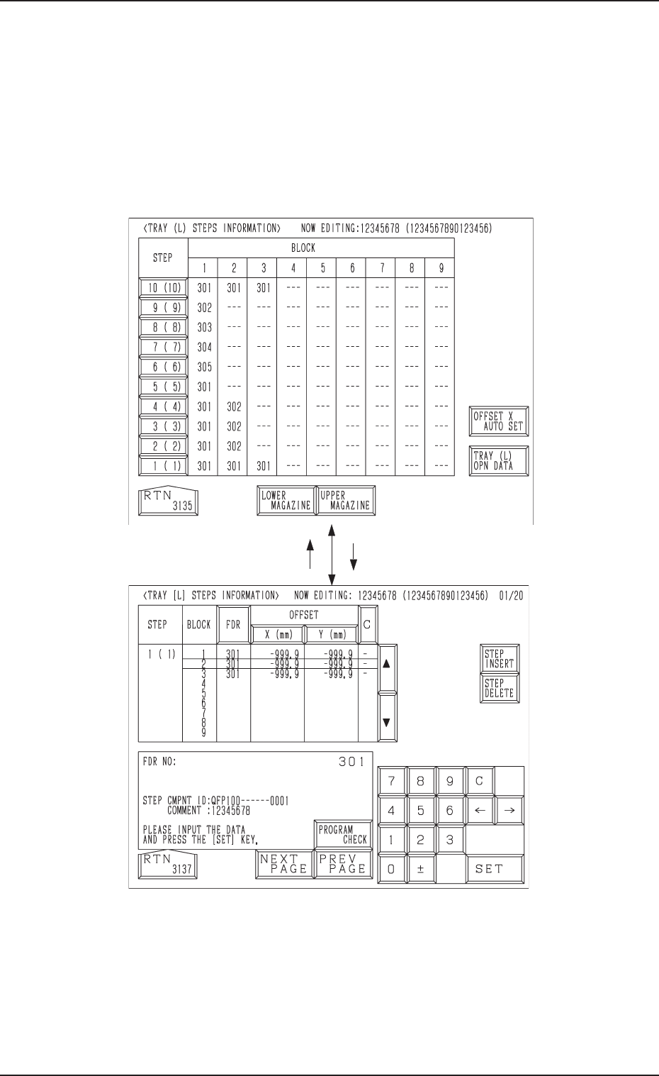
5.1.2.2 Tray Steps Information
Refer to “2.5.4 Tray Step Information (Option) of Section 2 in Volume 2” and
“4.5.3 Editing of Tray Steps Information Data (Option) of Section 2 in Vol-
ume 2” in the main machine instruction manual for details.
(1) When the [TRAY STEP INFO] key is pressed at the display (Fig. A17),
the display (Fig. A19) appears on the screen.
(2) Specify what type of components (FDR NO) you should set in which
block of which step with the tray unit.
Fig. A20
Fig. A19
5.1 Preparation (Outline) for Pattern Program
[1 ( 1)] Key[RTN] Key
0305-001 Chapter 1 2-10 Tg0869-PM-OM
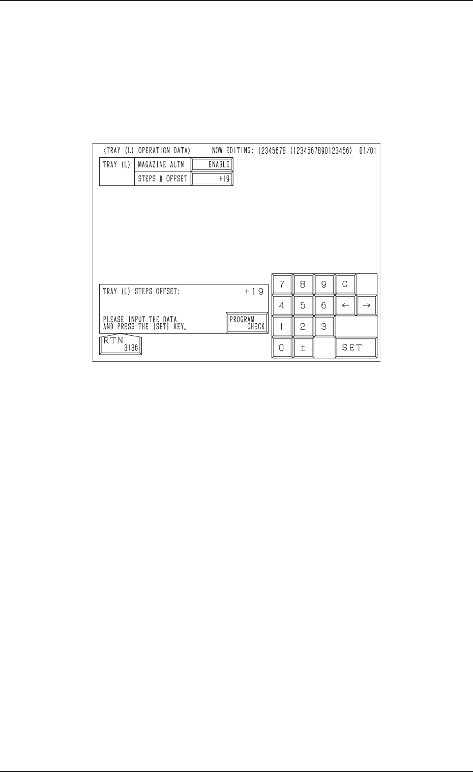
5.1.2.3 Tray (L) Operation Data
Refer to “2.5.5 TRAY (L) OPERATION DATA Display (Option) of Section 2
in Volume 2” and “4.5.4 Editing of Tray (L) or (R) Operation Data (Option) of
Section 2 in Volume 2” in the main machine instruction manual for details.
(1) When the [TRAY (L) OPN DATA] key is pressed at the display (Fig.
A19), the display (Fig. A21) appears on the screen.
• Set an operation mode.
Fig. A21
5.1 Preparation (Outline) for Pattern Program
0305-001 Chapter 1 2-11 Tg0869-PM-OM