OM-1012-001.pdf - 第253页
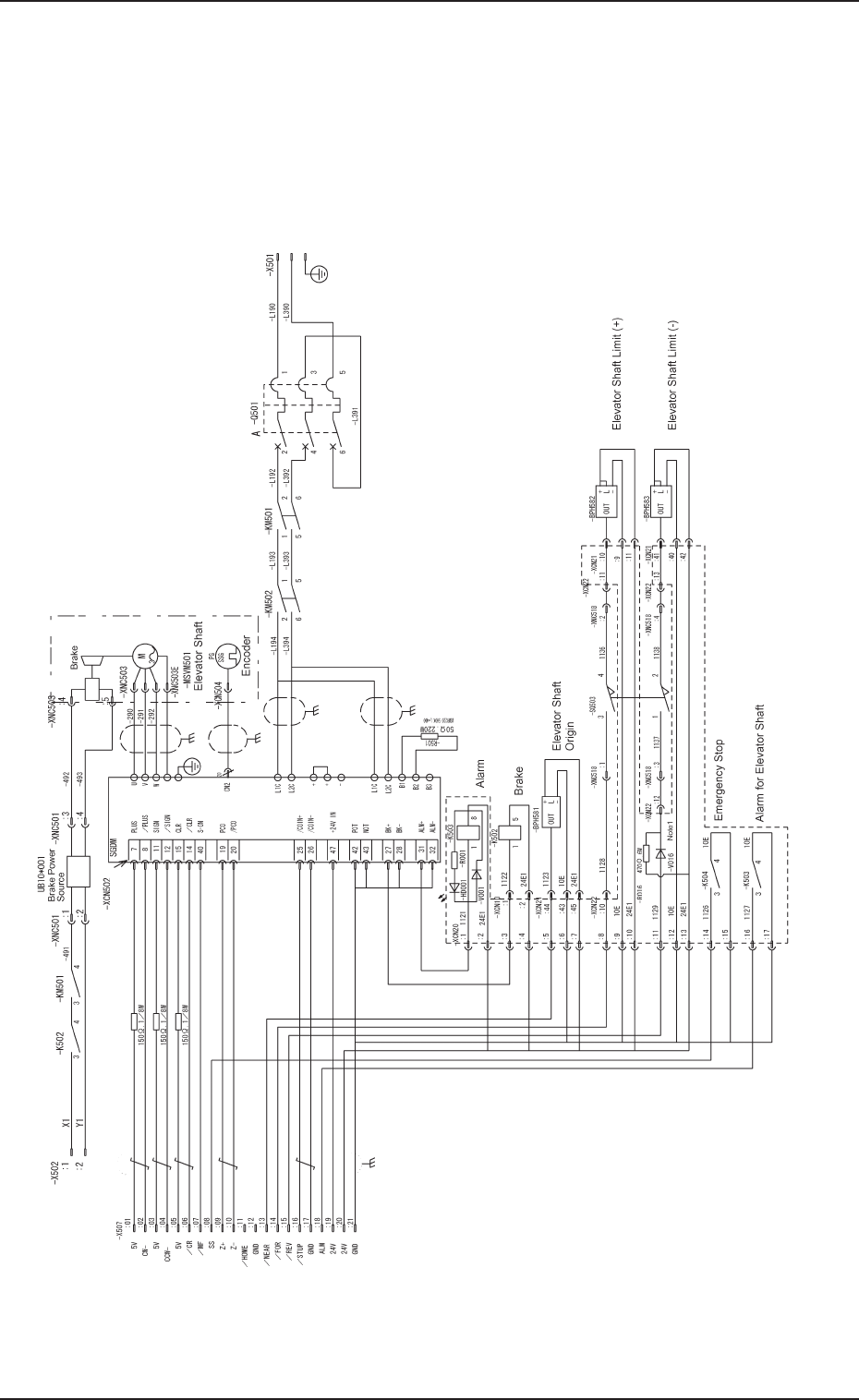
Chapter 5 2-16 Tg0869-PM-OM 0305-001A(M807WTR--0001) 3. Electrical Circuit Diagrams (FP-5022R) 3.1 Elevator Circuit Diagram 3. Electrical Circuit Diagrams (FP-5022R) Note : It shows the diagram within the dotted lines is…
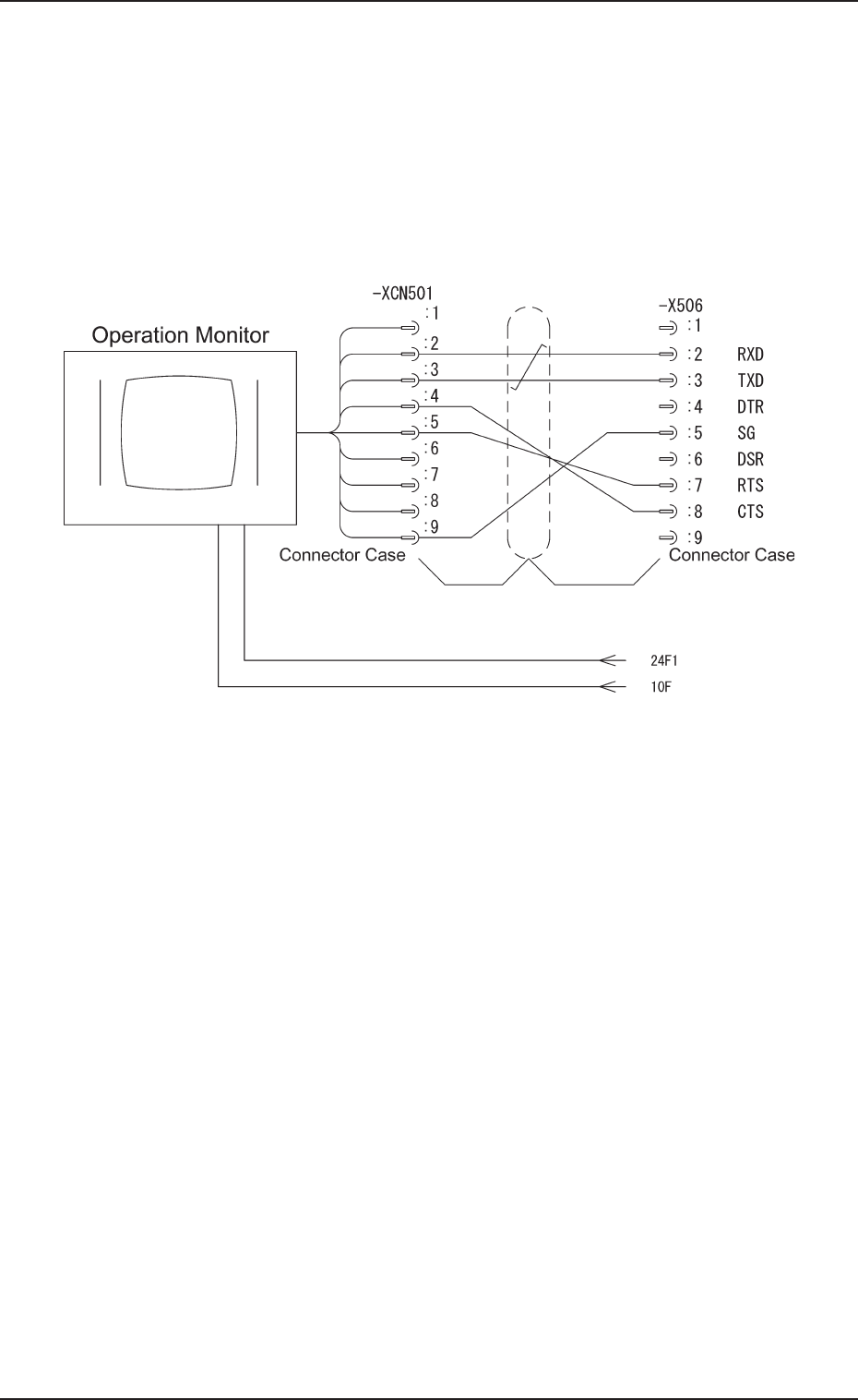
Chapter 5 2-15 Tg0869-PM-OM0305-001-(M807WTL--0007)
2.7 Operation Monitor Circuit Diagram
2.7 Operation Monitor Circuit Diagram
Chapter 5 2-16 Tg0869-PM-OM
0305-001A(M807WTR--0001)
3. Electrical Circuit Diagrams (FP-5022R)
3.1 Elevator Circuit Diagram
3. Electrical Circuit Diagrams (FP-5022R)
Note : It shows the diagram within the dotted lines is
within the relay PCB.
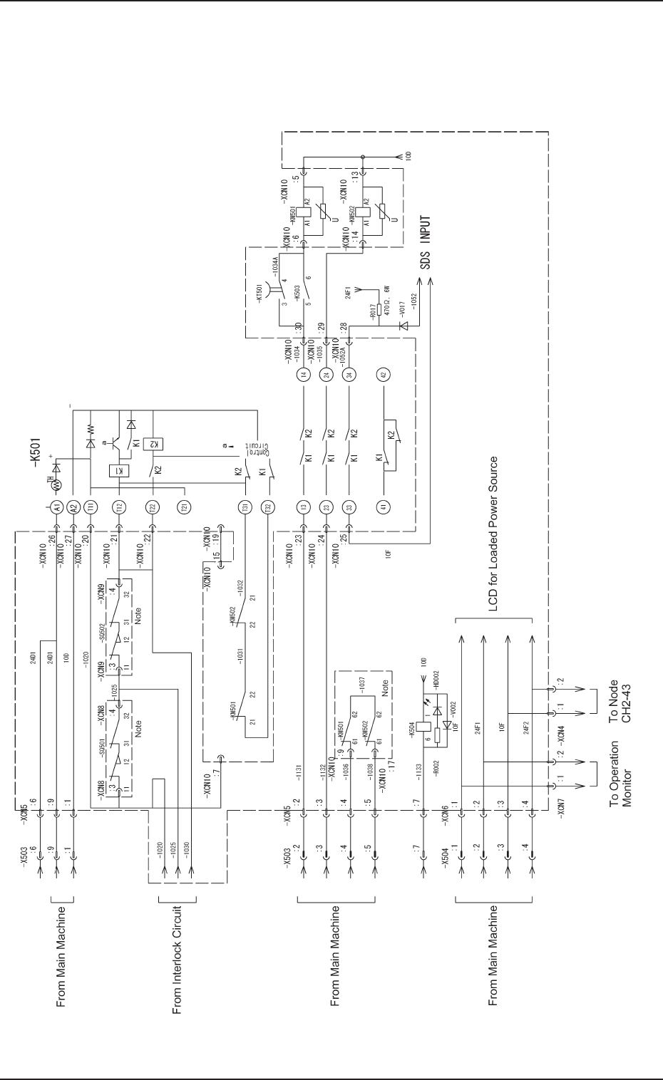
Chapter 5 2-17 Tg0869-PM-OM
0305-001-(M807WTR--0002)
3.2 Power Supply Circuit Diagram 1
3.2 Power Supply Circuit Diagram 1
Note : It shows the diagram within dotted lines is within the
relay PCB.