4OM-1429-008_w.pdf - 第109页
1-48 0707-001 4.1 Cleaning of V acuum Nozzles Ultrasonic Cleaning Method • Set the nozzles in a nozzle cleaning jig as one shown in the fi gure below and dip the jig low in the ultrasonic cleaner with water . Keep it in t…
1-47
0707-001
4.1 Cleaning of Vacuum Nozzles
Cleaning Method
Procedure
(1) Store the nozzle in the nozzle stocker (housing) through window
navigations and take out the nozzle stocker (housing).
Notice
Do not take out a nozzle from the head by hand. Otherwise, the
nozzle does not conform to the nozzle data.
Reference
Refer to "6. "Nozzle Change" Window" in "Chapter 3 (Vol. 2)" for the
procedure of nozzle storage.
(2) Blow air to remove dust and dirt.
At this time, use clean, dry, and non-lubricated air.
Clean the tapered area of the nozzle with a lens cleaning cloth.
When the tapered area is extremely dirty, brush the nozzle end 20 to 30
times with a toothbrush and then clean the nozzle in the water with an
ultrasonic cleaner.
When a recognition error occurs frequently, rub the back of the collar
approximately 20 times with a toothbrush.
Notice
(a) Do not blow air to the nozzle being attached to the head.
Doing otherwise may cause the filter to pop out of the head.
The filter may damage the head.
(b) Do not use anything other than water for the cleaning.
Note
Demagnetize the vacuum nozzle after the detachment.
Keep the head section free of any magnetic field.
As an example,
•
Do not bring a magnet close to the head section.
•
Do not bring any demagnetizer to the head section.
1-48
0707-001
4.1 Cleaning of Vacuum Nozzles
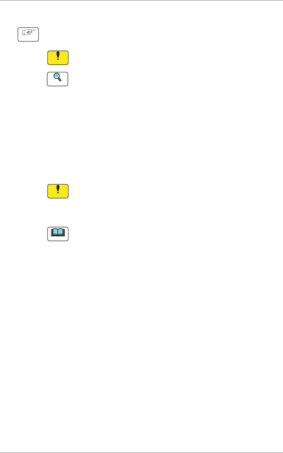
Ultrasonic Cleaning Method
•
Set the nozzles in a nozzle cleaning jig as one shown in the fi
gure below
and dip the jig low in the ultrasonic cleaner with water.
Keep it in the jig for approximately 15 minutes for the cleaning.
Note
The nozzle cleaning jig must be prepared on the customer side.
•
After washing with the ultrasonic cleaner, blow air to the nozzles.
When the nozzles are not dry enough, wipe them with a rag.
Notice
When a nozzle is set in the jig, pay attention to the orientation of the
nozzle.
Ø3.5 (THRU)
(159)
12
12
12
12
12
12
12
12
12
12
12
13.5
15
10
15
15
(65)
10
15
13.5
10
Material: Duracon (POM)
Fig. 4A44-1 Nozzle Cleaning Jig (Example)
1-49
0707-001
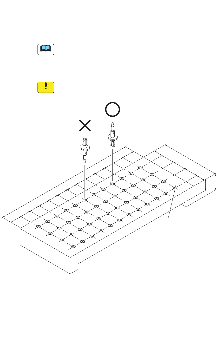
4.3 Replacement of Fluorine Sheet and Urethane Clamp
4.3 Replacement of Fluorine Sheet and Urethane Clamp
Time of Replacement
It is recommended that they should be replaced once a year.
Replacement Procedure
Procedure
(1) Zero the cutter.
Reference
Refer to "4.4 "CUTTER ADJ" Window" in "Chapter 4 (Vol. 2)" for
the zeroing operation of the cutter.
(2) Move down the feeder base and detach the bank feeder change
cart.
(3) Turn off the power to the machine.
(4) Open the cover.
(5) Detach the transparent cover (origin and motor sides) and the
tape guide.
Notice
(a) Carefully detach or attach the tape guide to avoid the
Y-axis linear scale being scratched.
(b) When the cutter is not located at its origin, the tape guide
cannot be detached because the fluorine sheet is caught
by the tape clamp.
Tape Guide
Transparent Cover
(Motor Side)
Transparent
Cover
(Origin Side)
Fig. 4A48