4OM-1429-008_w.pdf - 第110页
1-49 0707-001 4.3 Replacement of Fluorine Sheet and Urethane Clamp 4.3 Replacement of Fluorine Sheet and Urethane Clamp T ime of Replacement It is recommended that they should be replaced once a year . Replacement Proced…
1-48
0707-001
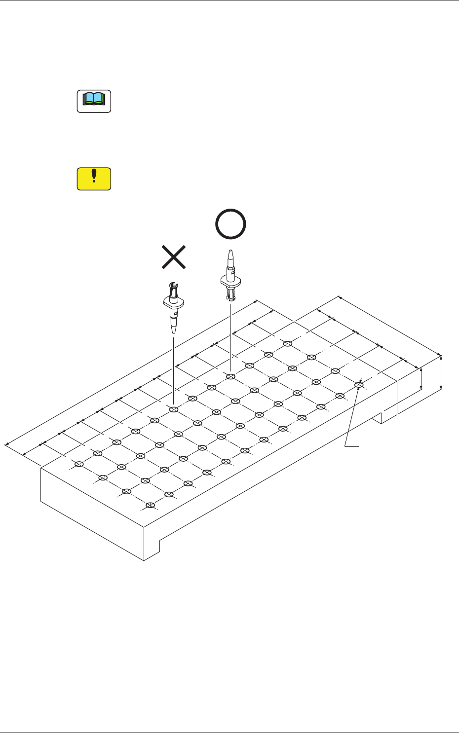
4.1 Cleaning of Vacuum Nozzles
Ultrasonic Cleaning Method
•
Set the nozzles in a nozzle cleaning jig as one shown in the fi
gure below
and dip the jig low in the ultrasonic cleaner with water.
Keep it in the jig for approximately 15 minutes for the cleaning.
Note
The nozzle cleaning jig must be prepared on the customer side.
•
After washing with the ultrasonic cleaner, blow air to the nozzles.
When the nozzles are not dry enough, wipe them with a rag.
Notice
When a nozzle is set in the jig, pay attention to the orientation of the
nozzle.
Ø3.5 (THRU)
(159)
12
12
12
12
12
12
12
12
12
12
12
13.5
15
10
15
15
(65)
10
15
13.5
10
Material: Duracon (POM)
Fig. 4A44-1 Nozzle Cleaning Jig (Example)
1-49
0707-001
4.3 Replacement of Fluorine Sheet and Urethane Clamp
4.3 Replacement of Fluorine Sheet and Urethane Clamp
Time of Replacement
It is recommended that they should be replaced once a year.
Replacement Procedure
Procedure
(1) Zero the cutter.
Reference
Refer to "4.4 "CUTTER ADJ" Window" in "Chapter 4 (Vol. 2)" for
the zeroing operation of the cutter.
(2) Move down the feeder base and detach the bank feeder change
cart.
(3) Turn off the power to the machine.
(4) Open the cover.
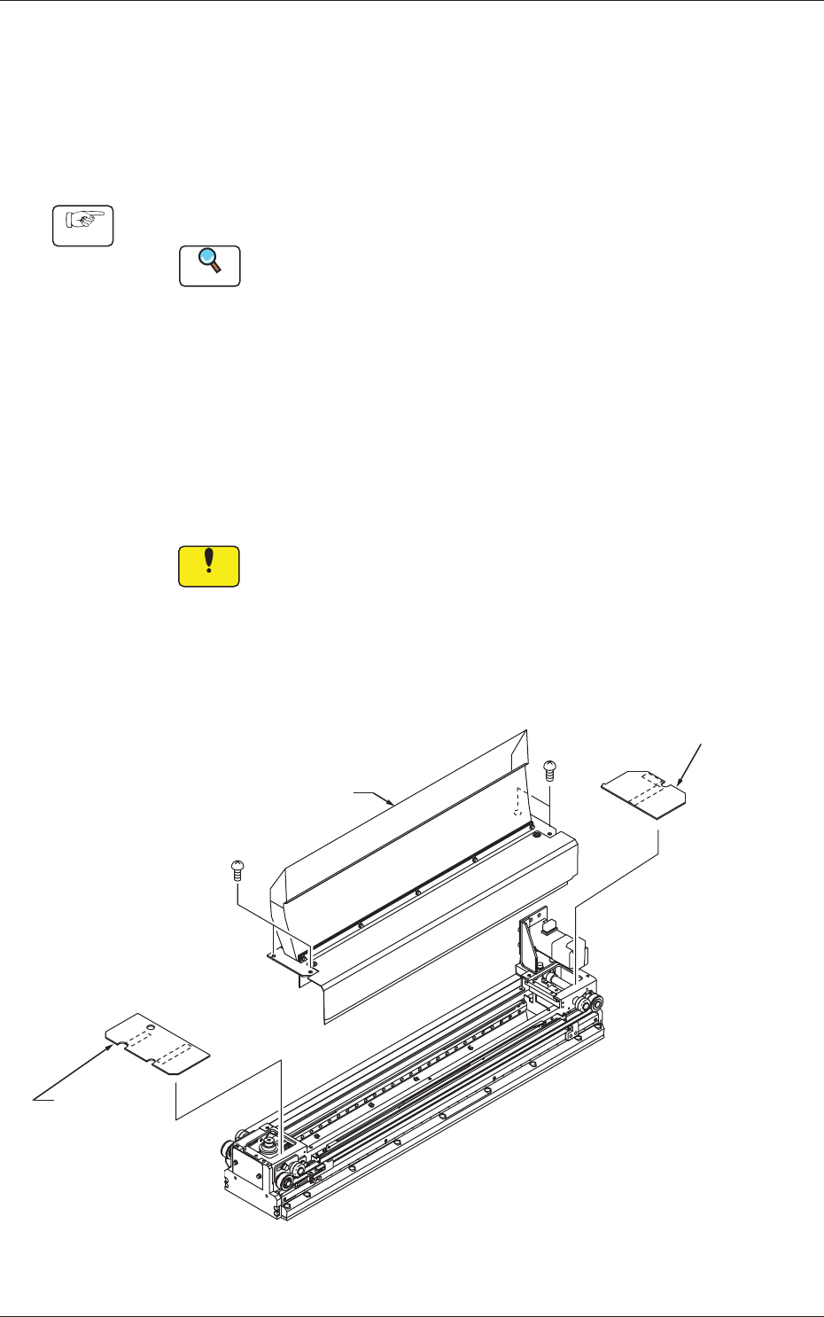
(5) Detach the transparent cover (origin and motor sides) and the
tape guide.
Notice
(a) Carefully detach or attach the tape guide to avoid the
Y-axis linear scale being scratched.
(b) When the cutter is not located at its origin, the tape guide
cannot be detached because the fluorine sheet is caught
by the tape clamp.
Tape Guide
Transparent Cover
(Motor Side)
Transparent
Cover
(Origin Side)
Fig. 4A48
1-50
0712-002
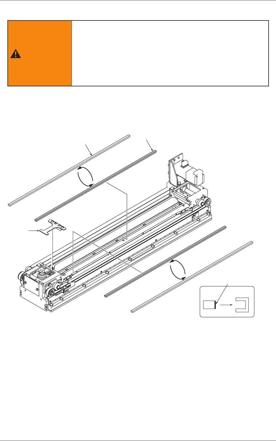
(6) Attach the cut unit fixing Jig.
WARNING
Pay close attention to the cutter blade during the maintenance
work.
•
Lack of attention will result in a hand injury, etc.
Wear gloves and take the greatest care in performing the work.
•
Be sure to attach the fixing jig to the cut unit during the
maintenance work for safety purposes.
(7) Detach the urethane clamp from the tape clamp.
(8) Peel off the double-faced tape of a new urethane clamp and
attach a new urethane clamp to the tape clamp.
New Urethane Clamp
Old Urethane Clamp
Double-Faced Tape Side
View (Attachment Direction)
from Side Face
Cut Unit
Fixing Jig
Fig. 4A49
4.3 Replacement of Fluorine Sheet and Urethane Clamp