4OM-1429-008_w.pdf - 第75页
1-16 0707-001 3. Maintenance Spots 3. Maintenance Spots 3.1 Whole View Notice Any operations with a cover(s) being removed are included. After the maintenance work, be sure to attach the cover . Feeder Cart Section Contr…
1-150707-001
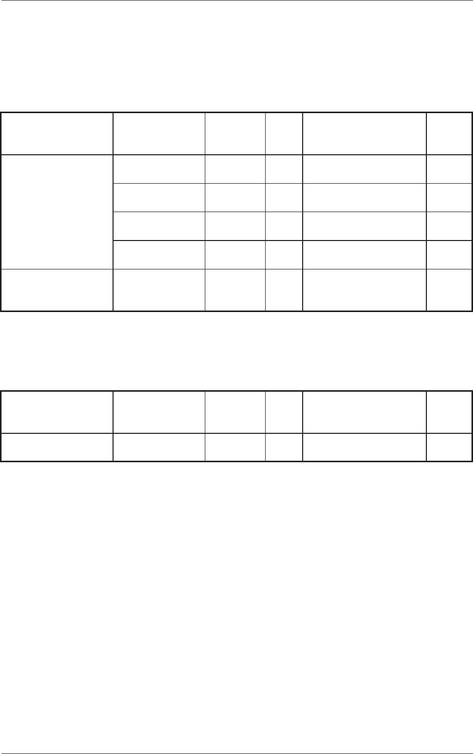
2.5 Half-Yearly Maintenance
Grease Symbols
DE1 : DAPHNE EPONEX GREASE No. 1
KS64 : Silicon Grease KS64
Table 4A12
Object Units
Inspection,
Cleaning, and
Lubricating Spots
Work Grease Required Tools Check
3.3.8 X/Y Beam Section
X-Axis Cable
Sideface
Cleaning,
Lubrication
KS64 Oiled Rag, Brush
X-Axis Cable
Fixing Places
Inspection ----- -----
Y-Axis Cable
Sideface
Cleaning,
Lubrication
KS64 Oiled Rag, Brush
Y-Axis Cable
Fixing Places
Inspection ----- -----
3.3.9 PCB Positioning
Section
Ball Screw Splines Cleaning,
Lubrication
DE1 Oiled Rag,
Hand Grease Gun,
T
ype H
2.6 Yearly Maintenance
Table 4A13
Object Units
Inspection,
Cleaning, and
Lubricating Spots
Work Grease Required Tools Check
3.3.6 Cutter Section
Fluorine Sheet,
Urethane Clamp
Replacement ----- Screwdriver
,
Cut Unit Fixing Jig
2.5 Half-Yearly Maintenance
1-160707-001
3. Maintenance Spots
3. Maintenance Spots
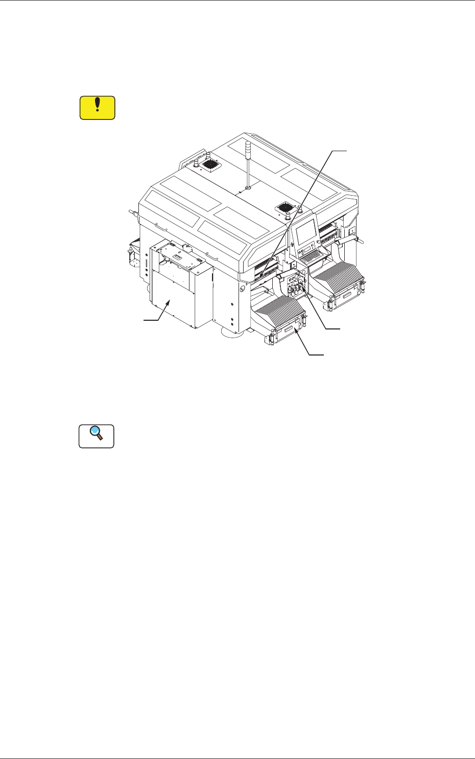
3.1 Whole View
Notice
Any operations with a cover(s) being removed are included.
After the maintenance work, be sure to attach the cover.
Feeder Cart Section
Control Box Section
Air Source
Vacuum System
Fig. 4A6 Front View of Machine
Reference
(a) Refer to "3.3" and the subsequent items for the detailed information
on the spots of each section to be maintained and how to maintain
them.
(b) As for the options, refer to each instruction manual of the specially
specified devices for the maintenance.
1-170707-001
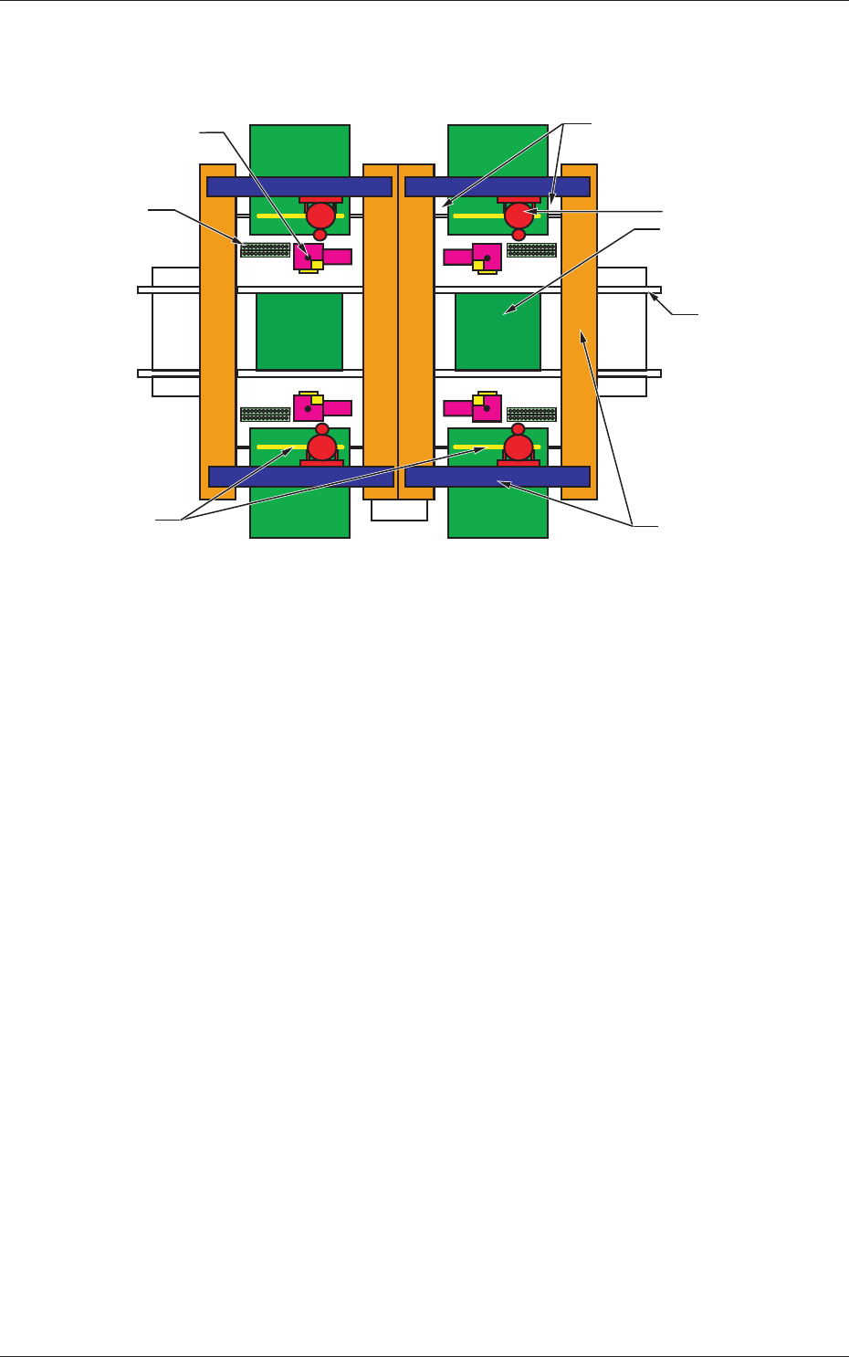
3.1 Whole View
(Front Side of Machine)
(Rear Side of Machine)
Component Recognition
Camera Section
Conveyor Section
PCB Positioning
Section
Head Section
X/Y Beam Section
Nozzle Stocker
Section
Cutter Section
Feeder Base Driving Section
Fig. 4A8