4OM-1429-008_w.pdf - 第128页
1-67 0904-003 5. Consumables and Important Servicing Parts 5. Consumables and Important Servicing Parts 5.1 List of Consumables Listed below are the parts that may be consumed within one year . Consult our marketing depa…
1-66
(5) Shake it in the rotational direction and confirm that the it does not
rotate. After that, pull out the filter replacement jig carefully so as not to
pull up the inserted filter together and stay afloat.
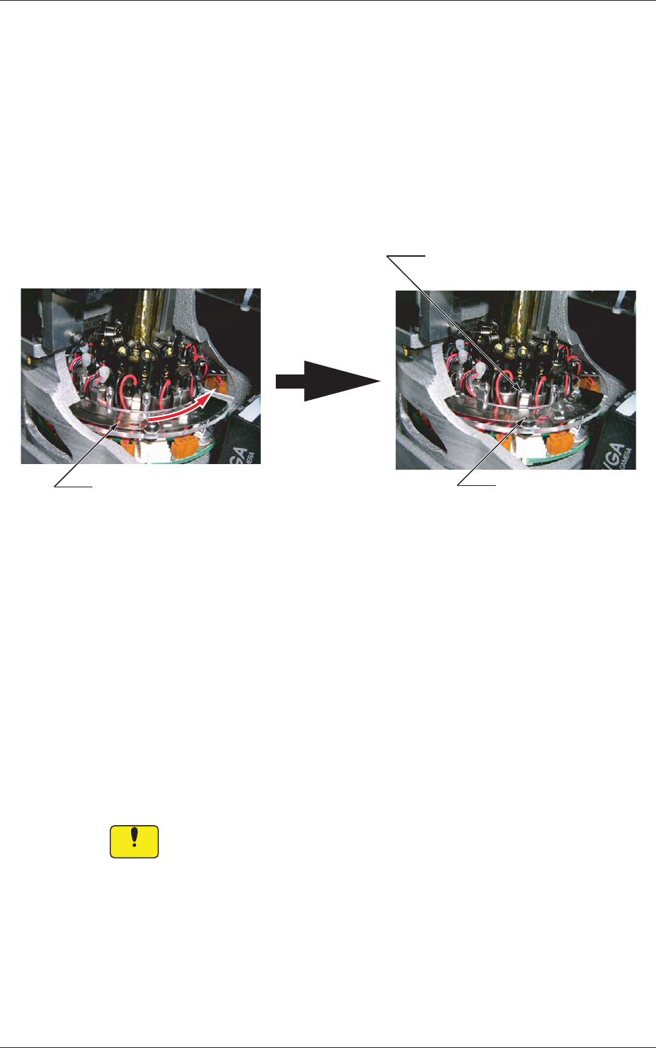
(6) Note the following and slide the filter fastener to the right to lock the
filter holder.
•
Confirm that the filter fastening claw is located at the upper
center of the filter holder
.
•
Confirm that the ball plunger is locked.
Ball Plunger Locked
Slide the filter fastener to the right.
Filter Unlocked Filter Locked
Locking Position of Filter
Fastening Claw
Filter Unlocked Filter Locked
Fig.
4A64
When the filter fastening claw cannot be locked after being slid because
it interferes with the sideface of the filter holder, it can be assumed that
a foreign substance exists in the hole or the filter holder is not inserted
sufficiently far into the hole.
Check the filter holder that has interfered with the sideface.
If a forei
gn sub
stance exists in the hole, clean the filter holder to remove
the substance.
After the cleaning is completed and no foreign substance is found in the
hole, starting with Step (4).
Notice
Unless the filter holder is set correctly in place, a pickup error will
occur or the filter will come off and cause an interference with a
head.
The head may also be damaged.
4.7 Replacement Procedure of Vacuum Filters
0707-001
1-67
0904-003
5. Consumables and Important Servicing Parts
5. Consumables and Important Servicing Parts
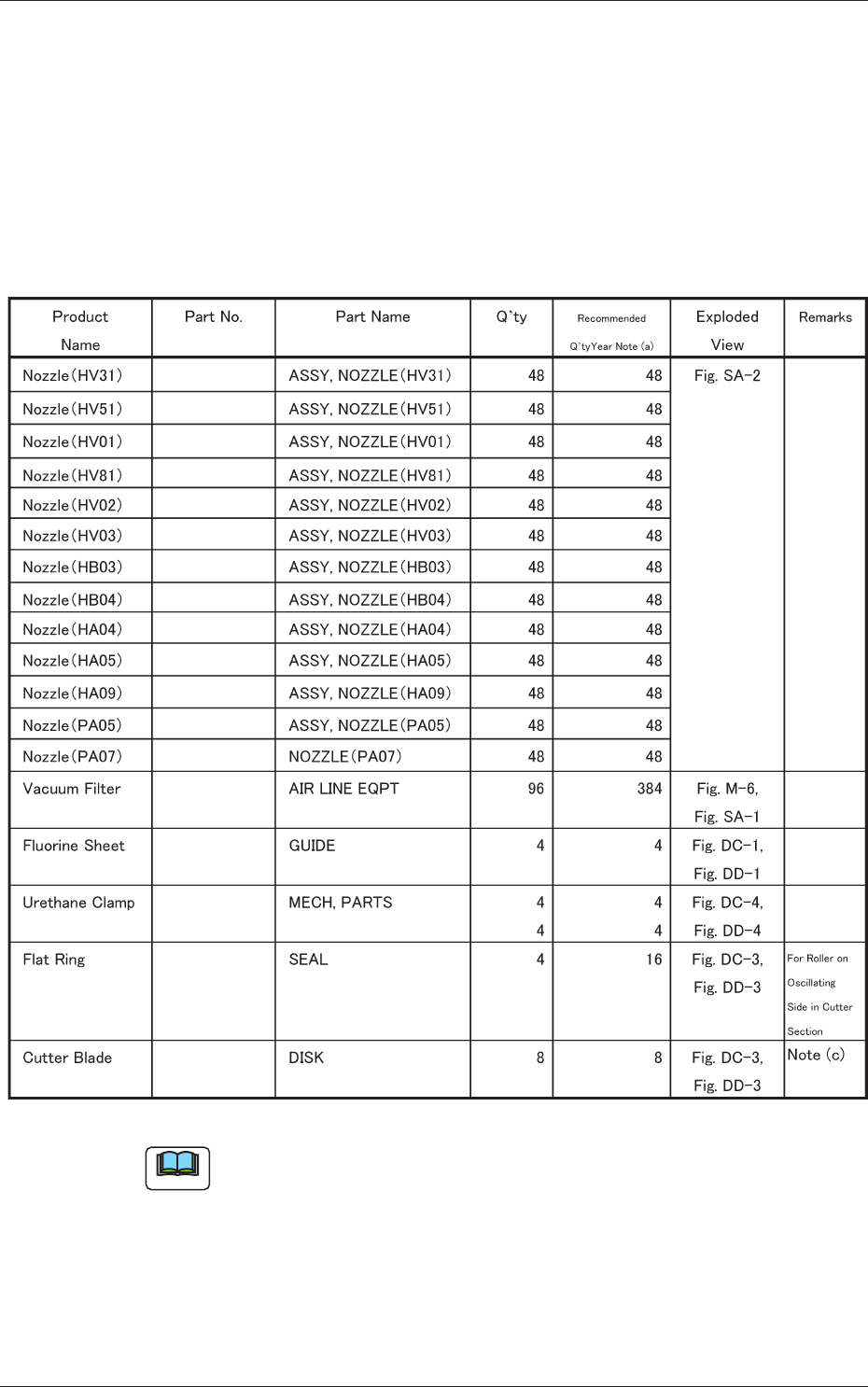
5.1 List of Consumables
Listed below are the parts that may be consumed within one year.
Consult our marketing department or sales agency whenever you need to
purchase these parts.
Table 4A14
016M1433
016M1434
016M0929
016M1482
016M0930
016M0931
016M0932
016M0933
016M0934
016M0935
016M1074
016M2168
225B0508
212A2219
226J2299
226J2403
226A0256
213D1294
016M0936
Note
(a) The numbers entitled "Recommended Q'ty/Year" indicate the
referential values.
(b) Refer to "3. Maintenance Spots" and "4. Maintenance Method" for the
replacement procedures of these parts.
(c) Replacement of the cutter blades involves some danger. Consult our
service personnel for detailed information.
1-68
0904-003
5.2 List of Important Servicing Parts
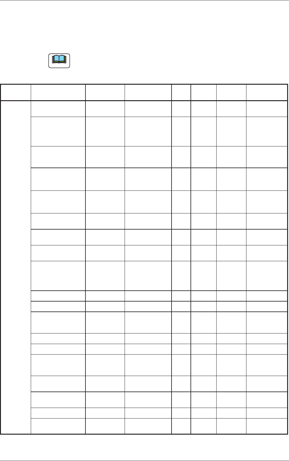
5.2 List of Important Servicing Parts
Listed below are the parts for which maintenance work is required in several
years. The list below is provided for your reference.
Note
Since replacement work of important service parts requires highly
sophisticated technique, consult our service personnel for details
Table 4A15
Block
Name
Product Name Part No. Part Name Q'ty
Recommended
Years
Note (a)
Exploded
View
Remarks
Head
Section
Solenoid Valve 23D10009 ACCESSORY,
SV
48 3 Fig. M-6
Nozzle Shaft
Assembly Nozzle
Shaft Diffusion Plate
(Small)
022L0011
222L0864
213D1166
ASSY,
GUIDE, LINEAR
GUIDE, LINEAR
DISK
48
Sets
(1)
(1)
――― Fig. M-6
Hexagon Socket
Head Bolts M2×6
221A0121 BOLT, HEX-SCT 96 ――― Fig. M-6
For Nozzle Shaft
Attachment
Note (b)
O Ring for Nozzle
Shaft
SO-010-19
226A0187 SEAL 96 2 Fig. M-6
O Ring for Nozzle
Shaft
SO-010-21
226A0105 SEAL 48 2 Fig. M-6
Spring for Nozzle
Shaft
222M1300 SPRING, COMP 48 ――― Fig. M-6
Packing for Nozzle
DYR-3
226A0189 SEAL 96 2 Fig. M-6
O Ring for Filter
SO-006-12
226A0127 SEAL 144 2 Fig. M-6
Linear Measure
Sensor
Linear Measure
Sensor Light Emitter
23G00302
23G00308
SENSOR, PELEC
SENSOR, PELEC
4Sets ――― Fig. M-6
Outer Diffusion Plate 213D1169 DISK 4 ――― Fig. M-6
Inner Diffusion Plate 213D1167 DISK 4 ――― Fig. M-6
Hexagon Socket
Head Bolt M1.6 × 4
221A0332 BOLT, HEX-SCT 28 ――― Fig. M-6
For Diffusion Plate
Attachment
Note (b)
Top Block 211G4547 BLOCK 48 ――― Fig. M-6
Cam Follower (φ2.5) 222H0134 CAMFOLLOWER 48 ――― Fig. M-6
Hexagon Socket
Head Bolt M1.6 × 3
221A0331 BOLT, HEX-SCT 96 ――― Fig. M-6
For Top Block
Attachment
Note (b)
Sensor PM-L24 23G10059 SENSOR,
PHOTO
4 3 Fig. M-4
Sensor PM-F24 23G10087 SENSOR,
PHOTO
20 3 Fig. M-2,3
Slip Ring 223C0201 COUPLING 4 2 Fig. M-5
Servo Motor 0860A000 MOTOR,
AC-SERVO
4 2 Fig. M-3