KE-750_MAINTE.pdf - 第103页
- 100 - 3.10 Laser Recognition Error How to act for the error status output from Laser Align is specified. In accordance with the error types, actions are classified as follows: Laser retry error: For this error ty pe, l…
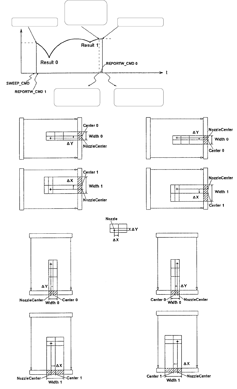
③ Measurement
- 99 -
Issuing SWEEP_CMD
↓
Starting rotation of θ axis
↓
Issuing REPORTW_CMD 1
↓
(Waiting the result)
↓
Obtaining Result 1
↓
Issuing REPORTW_CMD 0
↓
Obtaining Result 0
Completing
computation of
Result 1
Start of rotation End of rotation
Obtaining the
result of Result 1
Obtaining the
result of Result 0

- 100 -
3.10 Laser Recognition Error
How to act for the error status output from Laser Align is specified. In
accordance with the error types, actions are classified as follows:
Laser retry error: For this error type, laser measurement conditions (laser
height or pre-load angle) are automatically changed, and laser retry is
performed.
Production halt error: For this error type, production is put in a halt, and the
operator is asked to check the entered data and the status of the sensors.
Reset/power on again error: For this error type, it is necessary to terminate
production, send the reset command to the sensor, and turn off the power
and turn on it again.
Hardware replacement error: For this error type, the hardware of Laser Align
is faulty, and the sensor head or the SCM board has to be replaced.
Software fault error: For this error type, the software of Laser Align is faulty,
and it is necessary to ask CyberOptics for further investigation.
Other errors: Any error types other than those described above. It is the
hardware or software error whose cause is not Laser Align (mainly of JUKI).
Details of errors and actions
Laser retry error
Error code Cause of error Action
05
Link Error
An error occurred on the serial line
from the Laser Align sensor to the
SCM board. The cause is noise or
disconnection of the circuit to the
sensor.
Retry (of measurement). It is assumed
that a connection error occurs if the
same error occurs. Check the
connection. If not recovered, it is
assumed that hardware fault occurred,
and it is necessary to replace.
64
No Component
The Laser Align has not detected the
part. The cause is a part pick fault or
incorrect laser detection height (Z axis
height). The real cause is a fallen
part because part detection has been
performed with Measure Once
command before part scanning.
This occurs when the part falls down.
Or, re-check the laser height of part data
and setup data because the laser height
of the Z axis or the part height may not
be normal.
66
Minimum Width
Occurred at Start
of Scan
The minimum angle occurred when
scanning starts. The minimum angle
could not be detected because the
preload angle is too small or the
shape of the corners of the part is
round. If this occurs with the part
whose shape of the corners is round,
the part mount angle may be
incorrect. (In case when the 1st
angle is set in the longitudinal
direction of the part.)
If this occurs again after 1st retry,
temporarily stop the production and
check that the part feed angle and part
size of the part data are correctly
entered.

- 101 -
67
Scan Aborted
Before detecting the minimum width,
any command other than REPORTW
command has been sent and
scanning is interrupted. This can
occur when the nozzle is blocked by
the laser.
If this occurs again after retry, the data
entered can be largely incorrect.
Temporarily stop the production, and
check the part height of the part data. If
the error is not recovered, the height of
the nozzle of the Z axis is incorrect.
Check again the laser height.
71
Too Many Edges
Only the lead part at the bottom of the
plastic body of PLCC, etc. is detected.
If this occurs again after retry, the data
entered can be largely incorrect.
Temporarily stop the production, and
check the part height of the part data. If
the error is not recovered, the height of
the nozzle of the Z axis is incorrect.
Check again the laser height.
80
Left Edge of
Window Blocked
The part is too large with respect to
the window width, and the edge at the
left has been blocked. Normally,
when the appropriate size part is
used, the pick up position is largely
different and the window was blocked
during measurement.
If the part size does not exceed the
maximum applicable size, check whether
the pick position is largely different.
81
Right Edge of
Window Blocked
The same as above, the edge at the
right has been blocked.
Ditto
82
Both Edges of
Window Blocked
The same as above, the edges at the
left and right have been blocked.
Ditto
97
End Min
The minimum width has been
detected at the scanning end. This
can happen when the laser detects
the nozzle, not the part.
The same process as Scan Aborted.
98
Scan Limit
Before detecting the minimum width,
the angle exceeded the specified
value. This can happen when the
nozzle was blocked by the laser.
The same process as Scan Aborted.
Production interruption error
Error code Cause of error Action
06
Dirty Sensor
Windows
The sensor window is dirty. Clean the window. After cleaning is
complete, obtain again the laser height of
the nozzle.
65
Processor Unable
to Keep Up with
Frame Rate
The processor of Laser Align does not
follow the frame rate. In other words,
the data speed entered is too fast,
and measurement is impossible.
This can occur when the part is not
correctly picked, and there are too
many changes in the shade.
Check the pick position if the part is
correctly picked.