KE-750_MAINTE.pdf - 第114页
3.13 Bad Mark Detection The bad mark detection is performed as follows: ① Move the X-Y axes to the bad mark det ection coordinate. In this case, when starting movement, the LED of the bad mark sensor is simultaneously tu…
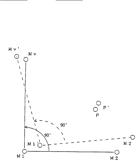
Angular correction value θ can be obtained as the angle made by vectors
(M1→P) and (M1'→P'). So, it can be obtained as follows:
(x' - x1')
(Y' - y1')
(xp - x1)
(yp - y1)
- atan ( )θ = atan ( )
For the BOC mark of two points (the same for IC mark)
As shown in the figure above, the theoretical coordinate of the BOC mark of two
points is defined M1 and M2, and the coordinate where each mark is detected is
defined M1' and M2'. In this case, coordinate Mv is where point M2 is rotated
by 90° with point M1 set at the center, and coordinate Mv' is where point M2' is
rotated by 90° with point M1' set at the center. Using Mv and Mv' as the
theoretical coordinate of the 3rd BOC mark which is virtual point, and using M1,
M2, M1', and M2' as the physical coordinate, in the same manner as the BOC
mark of three points, coordinate correction can be made by obtaining the
coordinate of point P' from the coordinate of point P.
- 110 -
3.13 Bad Mark Detection
The bad mark detection is performed as follows:
① Move the X-Y axes to the bad mark detection coordinate. In this case,
when starting movement, the LED of the bad mark sensor is simultaneously
turned on.
② When damping of the X-Y axes is complete, the status of the bad mark
sensor is read, and execution or skip of the circuit is recorded. Then, the
LED of the bad mark sensor is turned off.
③ Steps ① to ② are repeated from circuit No.1 to the last circuit.
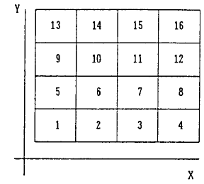
The order of the circuits subject to bad mark detection is the same as the one
for the BOC mark. For non-matrix split boards, the order of the number is the
one for the circuit location input from the board data input. For matrix split
boards, it is to be counted in an increasing order of the X axis at the side of the
circuit close to the machine origin of the X axis. This is repeated in increasing
order of the Y axis from the machine origin side of the Y axis. (See the figure
below.)
- 111 -
3.14 Feeder Drive Timing Chart
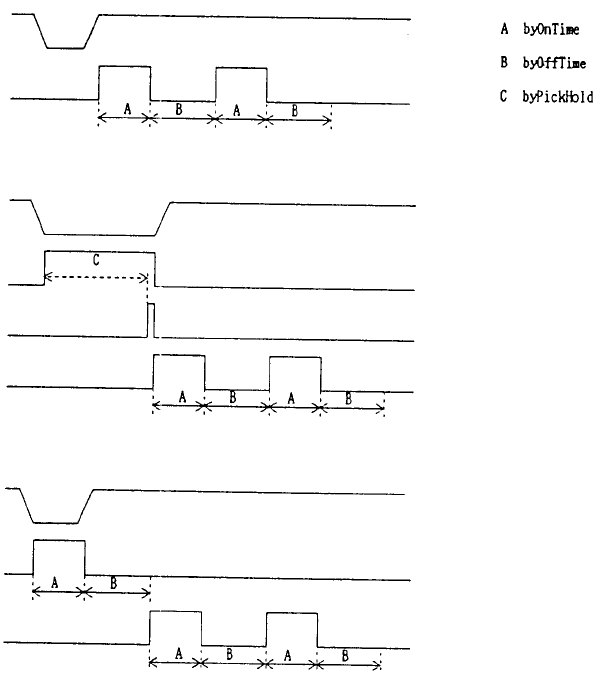
When standard feed is performed (Forward
only
)
Z Up
Down
Knock for feeder send
When pick attitude is to be held
Z down
Waiting time for arrival
Vacuum check
Knock for feeder send
When push up knock to the part is required (44 mm)
Z down
Knock for push up
Knock for feeder send
- 112 -