KE-750_MAINTE.pdf - 第80页
- 77 - 3.3.2 Nozzle replacement check Before and after detaching the nozzle and also before and after attaching the nozzle, laser align is performed to check whether the nozzle is installed in the Z slider shaft (nozzle …
- 76 -
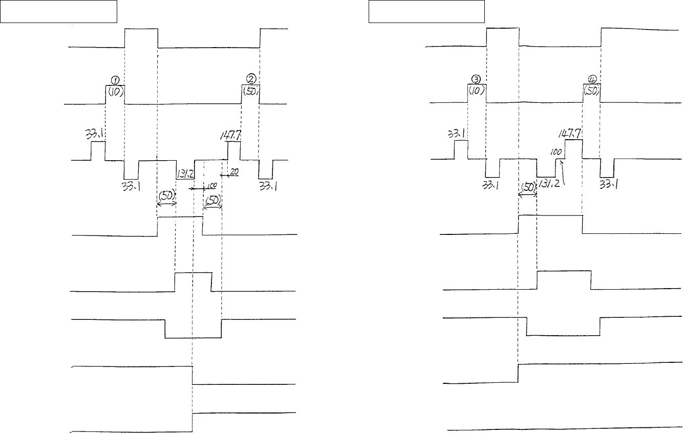
ATC replacement operation timing (KE-760) Replacement of the nozzle dedicated to the laser
When detaching When attaching
Move
X-Y
Stop
Nozzle YES/NO
check
Lift up
Z axis Stop
Lift down
Open
Slide plate
Close
ON
Open sensor
OFF
ON
Close sensor
OFF
ON
Vac
OFF
ON
Blow
OFF
Move
X-Y
Stop
Nozzle YES/NO
check
Lift up
Z axis Stop
Lift down
Open
Slide plate
Close
ON
Open sensor
OFF
ON
Close sensor
OFF
ON
Vac
OFF
ON
Blow
OFF
Standby
position
Laser
height
ATC
replacement
height
Move to ATC
NOTE: Time in parentheses ( ) is an assumed value.
NOTE: When both are replaced at the same time, the next
sequence occurs using the axis which is the longest
one for the pulse of Z axis to complete as the trigger.
Laser
height
Standby
position
Standby
position
Move to ATC
Standby
position
Laser
height
ATC
replacement
height
Standby
position
Standby
position
Laser
height
- 77 -
3.3.2 Nozzle replacement check
Before and after detaching the nozzle and also before and after attaching the
nozzle, laser align is performed to check whether the nozzle is installed in the Z
slider shaft (nozzle YES/NO check), and to check whether its operation has
been performed correctly.
For items q, w, and e for detaching and attaching, at 10 mm below the laser
height of the nozzle, whether the nozzle is attached to the Z slider shaft is
roughly checked by Measure Once command.
For item q, whether the nozzle is attached is checked before detaching.
For items w and e, whether the nozzle is detached is checked after detaching
and before attaching.
For item r, whether or not the nozzle is correctly attached is checked as follows:
When the nozzle is attached, at 0.4 mm below the laser height of the nozzle,
the diameter of the nozzle at the tip is measured by Measure Once command.
The measured result is regarded as normal when the measured diameter
equals to the specified value. If different, it is regarded as not normal, and an
error message is displayed. When normal, to check that the nozzle is set in
the Z slider shaft, the nozzle is moved by 0.3 mm up from the laser height, and
whether the nozzle is attached is checked again by Measure Once command.
When the nozzle is not detected (Status: 64), the result is normal. For any
other statuses, an error message is displayed regarding that the nozzle is not
normally attached.
If so, possible cause is lack of grease at the O-ring in the Z slider shaft, or a
foreign matter left between the nozzle and the Z slider shaft. Apply grease or
clean out the foreign matter.
3.4 Pick/mount operation (KE-750)
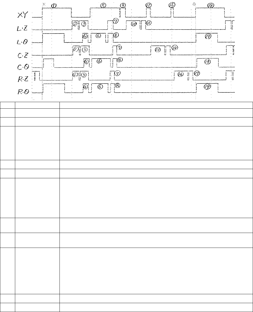
Simultaneous pick and alternate mount by three heads on KE-750 (0° pick-
180° mount)
No. Drive axis Operation
①
XY Moves from the mount position to the pick position.
②
LZ, CZ, RZ Moves down from the top standby position for part pick.
③
LZ, CZ, RZ After picking the part, moves up to the laser measurement height. After moved
up, vacuum check is performed to detect whether the part is set. If no part
status is detected, check is performed again by Measure Once command using
laser. If no part status is detected again, re-pick is performed with the number
of retries specified for part data.
④
Lθ, Cθ, Rθ
Pre-rotate (normally, 30°) is performed while the Z axis is moving up.
⑤
XY Moves from the pick position to the theoretical coordinate of the mount position.
⑥
Lθ, Cθ, Rθ
Laser measurement (150° rotation) is performed when XY is moving. When a
laser error occurs, laser measurement is performed again by setting the
pre-rotate angle to 40°. When the same error occurs again, the part is
discharged. When a correct measurement result is obtained, and when the
chip rise detection is set on, an operation for the detection is performed by
adjusting the Z axis to the chip rise detection height.
⑦
LZ, CZ, RZ Immediately after the laser measurement, moves from the laser measurement
height to the standby position at the top.
⑧
Lθ, Cθ, Rθ
Immediately after the laser measurement of each head, rotates for the mount
angle which is the measured result plus Δθ.
⑨
XY
After moving to the theoretical coordinate, moves by the offset of ΔX and ΔY
which is the result of the laser measurement of the L head. After movement is
complete, vacuum check is performed to detect whether or not the part is
picked. If no part status is detected, the Z axis is moved up. Then, the part is
adjusted to the laser height, and check is performed again by Measure Once
command using laser. If no part status is detected again, the part is
discharged and re-pick is performed.
⑩
LZ After stopping X and Y, the L head moves down immediately for mounting.
⑪
LZ The L head moves from the mount height to the standby position at the top.
- 78 -