KE-750_MAINTE.pdf - 第98页
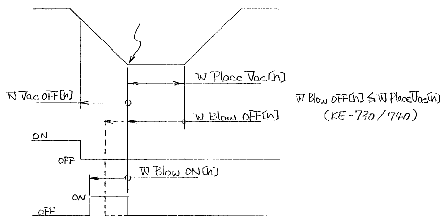
3.8.2.3 Vacuum and bl ow timing of KE-750/760 Figure 7 shows the operation timing of each SV of vacuum and blow on KE-750/760, and the changes in t he pressure values at the tip of the nozzle at that timing. Vacuum Blow …
Z axis
Vacuum
Blow
Height of part mount
Dashed line indicates the
change made on KE-750/760
On KE-750/760, to effectively use the blow, the timing to turn off the blow can
be set before completion of the downward movement of the Z axis. In this way,
the blow can be used at high vacuum pressure which is immediately after
turning off the vacuum, and the pressure in the nozzle can be changed from
negative to normal room atmosphere within a short time.
- 94 -
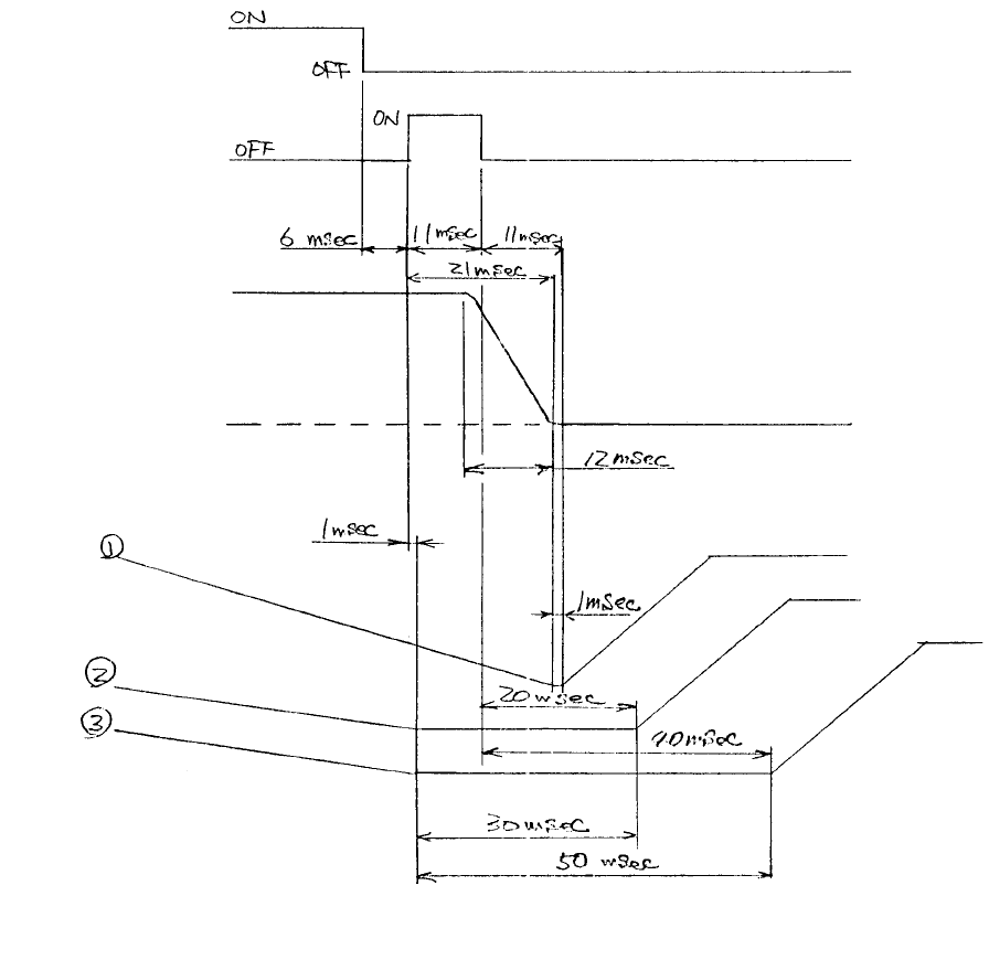
3.8.2.3 Vacuum and blow timing of KE-750/760
Figure 7 shows the operation timing of each SV of vacuum and blow on
KE-750/760, and the changes in the pressure values at the tip of the nozzle at
that timing.
Vacuum
Blow
Negative pressure
Vacuum level
Atmosphere
Z axis
Figure 7
NOTE:
For Z axis: q is for square chip parts; w is for Melf, aluminum electrolytic
capacitor, network resistor, trimmer, SOT, SOJ, SOP, and PLCC; e is for QFP,
TSOP, BGA, connector, and socket.
- 95 -
- 96 -
As shown in Figure 7, the timing of vacuum off and that of blow on/off are the
same regardless of the part types. However, the parameter values of the
vacuum timer in Figure 6 differ for the part type because, for the Z axis, the
speed to move down and the time to be held differ per part type.
By performing blow control, the vacuum destruction time is shortened from 5 ms
(for KE-730/740 as shown in Figure 1) to 12 ms. As a result, a high vacuum
pressure can be maintained for mounting chip parts immediately before their
mount. For other part types, a high vacuum pressure is maintained until the
nozzle stops at the low position. Then, after releasing the vacuum pressure,
the nozzle is moved upward.