KE-750_MAINTE.pdf - 第84页
⑫ XY Moves by adding the offset of Δ X and Δ Y which is the result of the laser measurement of the R head. After move ment is complete, vacuum check is performed to detect whether or not the part is picked. If no part st…
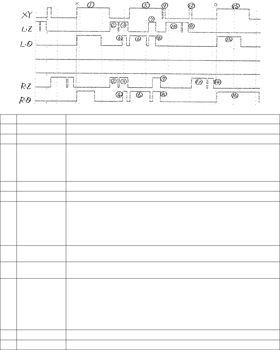
3.5 Pick/mount operation (KE-760)
Simultaneous pick and alternate mount by two heads on KE-760 (0° pick- 0°
mount)
No. Drive axis Operation
①
XY Moves from the mount position to the pick position.
②
LZ, RZ Moves down from the top standby position for part pick.
③
LZ, RZ After picking the part, moves up to the laser measurement height. After moved
up, vacuum check is performed to detect whether the part is set. If no part
status is detected, check is performed again by Measure Once command using
laser. If no part status is detected again, re-pick is performed with the number
of retries specified for part data.
④
Lθ, Rθ
Pre-rotate (normally, 30°) is performed while the Z axis is moving up.
⑤
XY Moves from the pick position to the theoretical coordinate of the mount position.
⑥
Lθ, Rθ
Laser measurement (150° rotation) is performed when XY is moving. When a
laser error occurs, laser measurement is performed again by setting the
pre-rotate angle to 40°. When the same error occurs again, the part is
discharged. When a correct measurement result is obtained, and when the
chip rise detection is set on, an operation for the detection is performed by
adjusting the Z axis to the chip rise detection height.
⑦
LZ, RZ Immediately after the laser measurement, moves from the laser measurement
height to the standby position at the top.
⑧
Lθ, Rθ
Immediately after the laser measurement of each head, rotates for the mount
angle which is the measured result plus Δθ.
⑨
XY
After moving to the theoretical coordinate, moves by the offset of ΔX and ΔY
which is the result of the laser measurement of the L head. After movement is
complete, vacuum check is performed to detect whether or not the part is
picked. If no part status is detected, the Z axis is moved up. Then, the part is
adjusted to the laser height, and check is performed again by Measure Once
command using laser. If no part status is detected again, the part is
discharged and re-pick is performed.
⑩
LZ After stopping X and Y, the L head moves down immediately for mounting.
⑪
LZ The L head moves from the mount height to the standby position at the top.
- 80 -
⑫
XY
Moves by adding the offset of ΔX and ΔY which is the result of the laser
measurement of the R head. After movement is complete, vacuum check is
performed to detect whether or not the part is picked. If no part status is
detected, the Z axis is moved up. Then, the part is adjusted to the laser
height, and check is performed again by Measure Once command using laser.
If no part status is detected again, the part is discharged and re-pick is
performed.
⑯
RZ After stopping X and Y, the R head moves down immediately for mounting.
⑰
RZ The R head moves from the mount height to the standby position at the top.
⑱
XY Moves from the mount position to the pick position.
⑲
Lθ, Rθ While X and Y are moving, returns each θ axis from the mount angle to 0°.
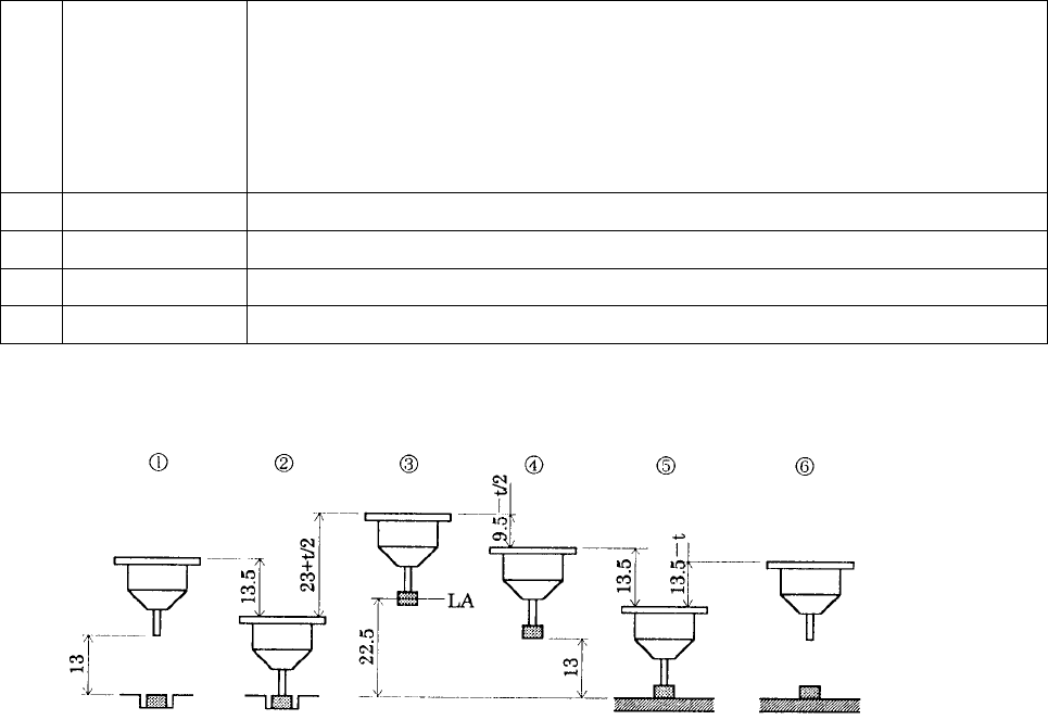
The figure below shows the production operation sequence. t in the figure is thickness of the
element.
Top surface of
the board
① First, at the pick position, the distance between the tip of the nozzle and the surface of the board
(the same as the top surface of the part to be picked) is 13 mm.
② Moves down by 13.5 mm to pick the part (13 mm + 0.5 mm of pushing amount which is a default
value and changeable as part data).
③ Moves up by (23 + t/2) mm so that the center (middle level) of the part is placed at the same level
as the laser surface which is 22.5 mm. This movement is a default setting, and it can be
changed as part data.
④ After measured by LA, moves down by (9.5 - t/2) mm so that the bottom tip of the part is set at 13
mm height.
⑤ Moves down by 13.5 mm which is the distance between the top surface of the board and the
bottom tip of the part, plus 0.5 mm (default value) which is nozzle pushing amount.
⑥ Moves up by (13.5 - t) mm so that the bottom tip of the nozzle is set 13 mm above the top
surface of the board.
- 81 -
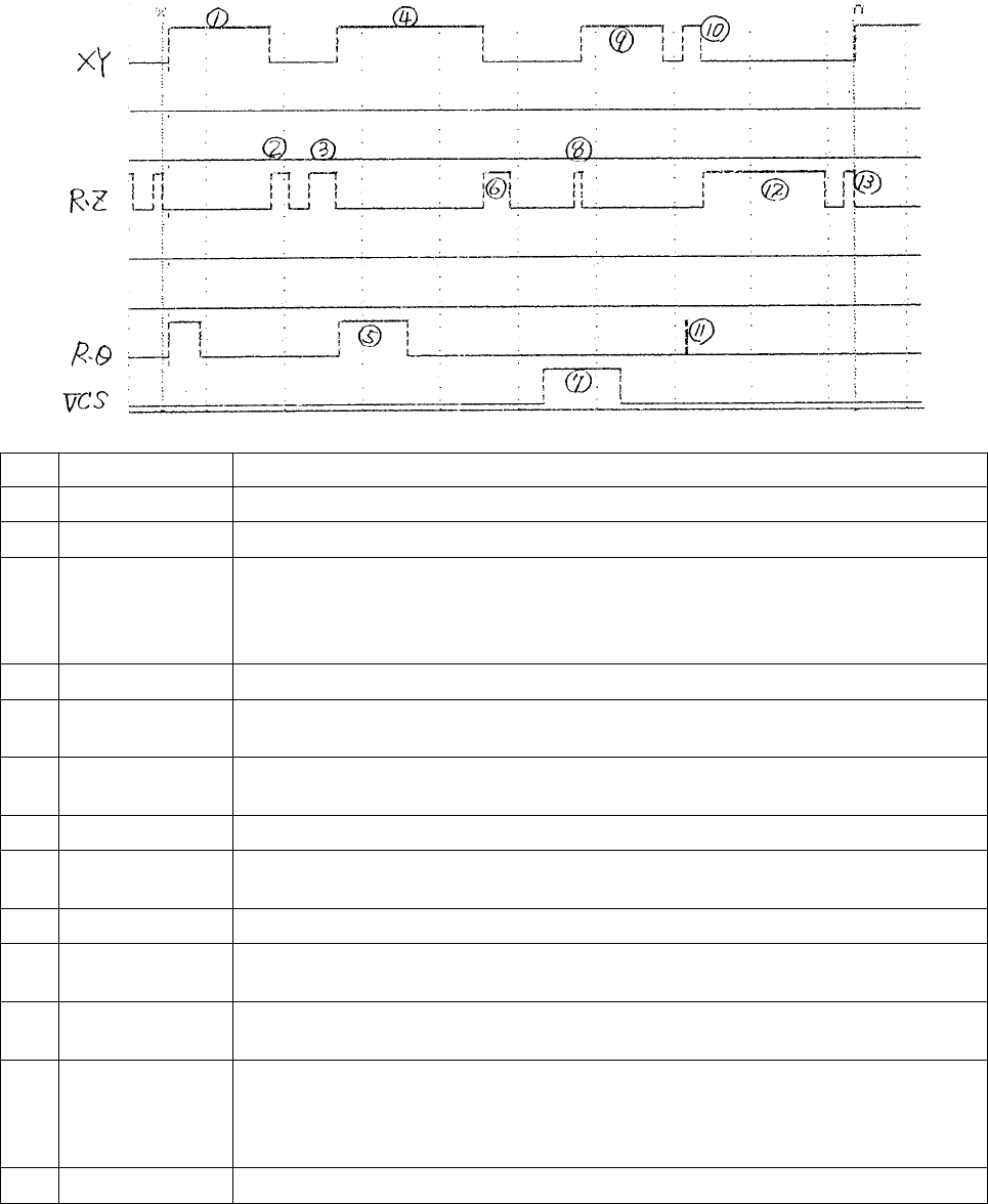
KE-760 Picture Recognition Mount
No. Drive axis Operation
①
XY Moves from the mount position to the pick position.
②
RZ Moves down from the top standby position to the pick height for part pick.
③
RZ After picking the part, moves the bottom surface of the part up to the standby
position at the top. After moved up, vacuum check is performed to detect
whether the part is set. If no part status is detected, re-pick is performed with
the number of retries specified for part data.
④
XY Moves the R head from the pick position to the vision recognition camera.
⑤
Rθ
At the same time when the X and Y axes start to move, rotate for the mount
angle.
⑥
RZ After the movement of the vision recognition camera is complete, the Z axis is
moved down so that the bottom tip of the part is set at the recognition height.
⑦
VCS Picture recognition and computation are performed.
⑧
RZ After vision recognition, the Z axis is moved up so that the bottom tip of the part
is moved from the recognition height to the standby position at the top.
⑨
XY After vision recognition, moves to the theoretical coordinate for the mount.
⑩
XY
After moving to the theoretical coordinate, moves by the offset of ΔX and ΔY
which is the result of the vision recognition computation. (Correction)
⑪
Rθ Rotates by the offset of Δθ which is the result of the vision recognition
computation.
⑫
RZ
After correcting X, Y, and θ, moves down for mount. Immediately before
moving down, vacuum check is performed to detect whether or not the part is
picked. If no part status is detected, the part is discharged and re-pick is
performed.
⑬
RZ The R head moves from the mount height to the standby position at the top.
- 82 -