KE-750_MAINTE.pdf - 第108页
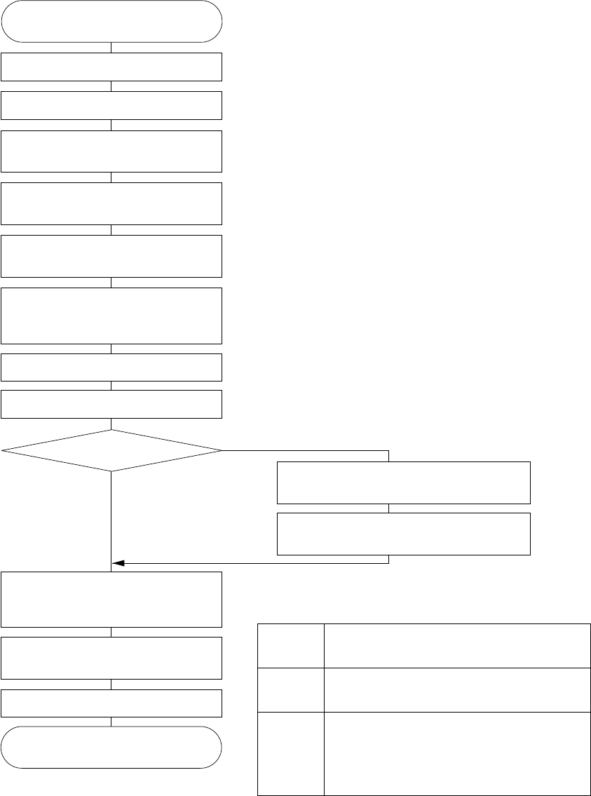
3.11 Part Recognition Process Part recognition using the VCS is performed as shown below: START Recognition result, received? Sends the switch command to the VCS camera for recognition Moves the X-Y, Z, and θ axes to the…

- 104 -
94
No Cutoff 1
Ditto Ditto
95
No Cutoff 2
Ditto Ditto
96
Constant Angle
Ditto Ditto
101
Page Mismatch
Spare. Consult CyberOptics. Ditto
Other errors
Error code Cause of error Action
07
No Algorithm
NO_ALG has been requested. Consult JUKI (Developer).
69
DPRAM
An error of Dual Port RAM. This is
impossible to happen because that
RAM is not used.
Ditto
72
More Pages
A
n error related to Window command.
This can occur when Window 1 has
been specified with SCM2. This is
impossible to happen because only
Window 0 is used.
Ditto
73
More Counters
This error can occur when encoder
No.1 has been specified with SCM2.
This is impossible to happen because
only encoder No.0 is available.
Ditto
74
More Windows
This error can occur when Window
No.1 has been specified with SCM2.
This is impossible to happen because
only Window No.0 is available.
Ditto
75
Previous Error
An error has occurred with the
previous algorithm.
Ditto
78
Small Window
The window size has been for set less
than 8 pixels.
Ditto
86
Bad Parameter
An invalid parameter has been set. Ditto
87
Bad Data
Invalid data has been detected. It is
necessary to check whether a valid
data has been included in the
program sequence or a command
error has occurred.
Ditto
93
Minimum Too High
The change in the curve to the angle
is too small. This is likely to occur
when a small part is turned at low
speed.
Ditto
100
Units Not Set
Required initialization has not been
performed yet.
Ditto
102
Invalid Algorithm
A invalid algorithm has been sent. Ditto
3.11 Part Recognition Process
Part recognition using the VCS is performed as shown below:
START
Recognition result, received?
Sends the switch command to the
VCS camera for recognition
Moves the X-Y, Z, and θ axes to the
part recognition unit.
Completes component pick.
Turns on the VCS light.
Sends the part recognition command
to the part recognition unit.
Completes the direct interruption from
the part recognition unit, and waiting
communication reception.
Turns off the VCS light.
Other operations
Obtains the mount coordinate with
which part recognition correction has
been completed.
Moves the X-Y, and θ axes to the
mount coordinate.
Performs mounting.
Moves the X-Y, and θ axes to the coordinate
before part recognition correction.
Waits the result of recognition from the
recognition unit.
End
NO
YES
*1
*2
*1: The coordinates of the axes when part recognition are
as follows:
*2: No action is expected in many cases where mounting is
performed in sequence with the general head which
performs pick and mount with the IC dedicated.
X-Y axes
Z axis
θ axis
The rotating center of the IC head is placed at
the recognition center for the VCS camera.
At the bottom end of the nozzle, and (10 mm
+ part height) from the board surface.
The most nearest direction of the part when
mounted from 0, 90, 180, or 270 degree with
respect to the direction where the direction of
the picked part matches the Y axis direction
of the VCS camera's image.
- 105 -
3.12 BOC Mark Recognition
Operation timing
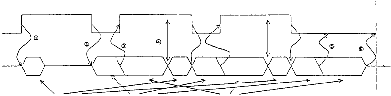
The figure below shows the operation timing of X-Y axes of the main unit and of
the recognition unit for BOC mark recognition.
To next action
X-Y axes
Recognition
unit
Camera change Image recognition Mark recognition
① When BOC recognition operation is started, the X-Y axes are started to
move to the BOC mark recognition position, and, at the same time, the
camera switch command to the BOC camera is sent to the recognition unit.
At this time, the BOC light turns on.
② When movement to the BOC mark recognition position is complete, the
BOC mark recognition command of the recognition unit is sent.
③ When the image recognition completion signal from the recognition unit is
received, the X-Y axes is started to move to the recognition position of the
next mark. After that, the mark recognition process is continued with the
recognition unit.
④ When the result of recognition from the recognition unit is received, the
camera switch command is sent again.
⑤ Steps ② to ④ are repeated until the last BOC mark. When the image of
the last BOC mark is obtained, the BOC light is turned off.
⑥ Waits the result of the image recognition of the last BOC mark from the
recognition unit, and performs the next action.
Recognition sequence
The sequence of BOC mark recognition is different between the BOC mark
recognition per board and the BOC mark recognition per circuit, and they are
performed as follows:
- For the BOC recognition per board
BOC mark recognition is performed from BOC mark position No.1, to No.2, to
No.3 which are shown as the board data.
- 106 -