KE-750_MAINTE.pdf - 第45页
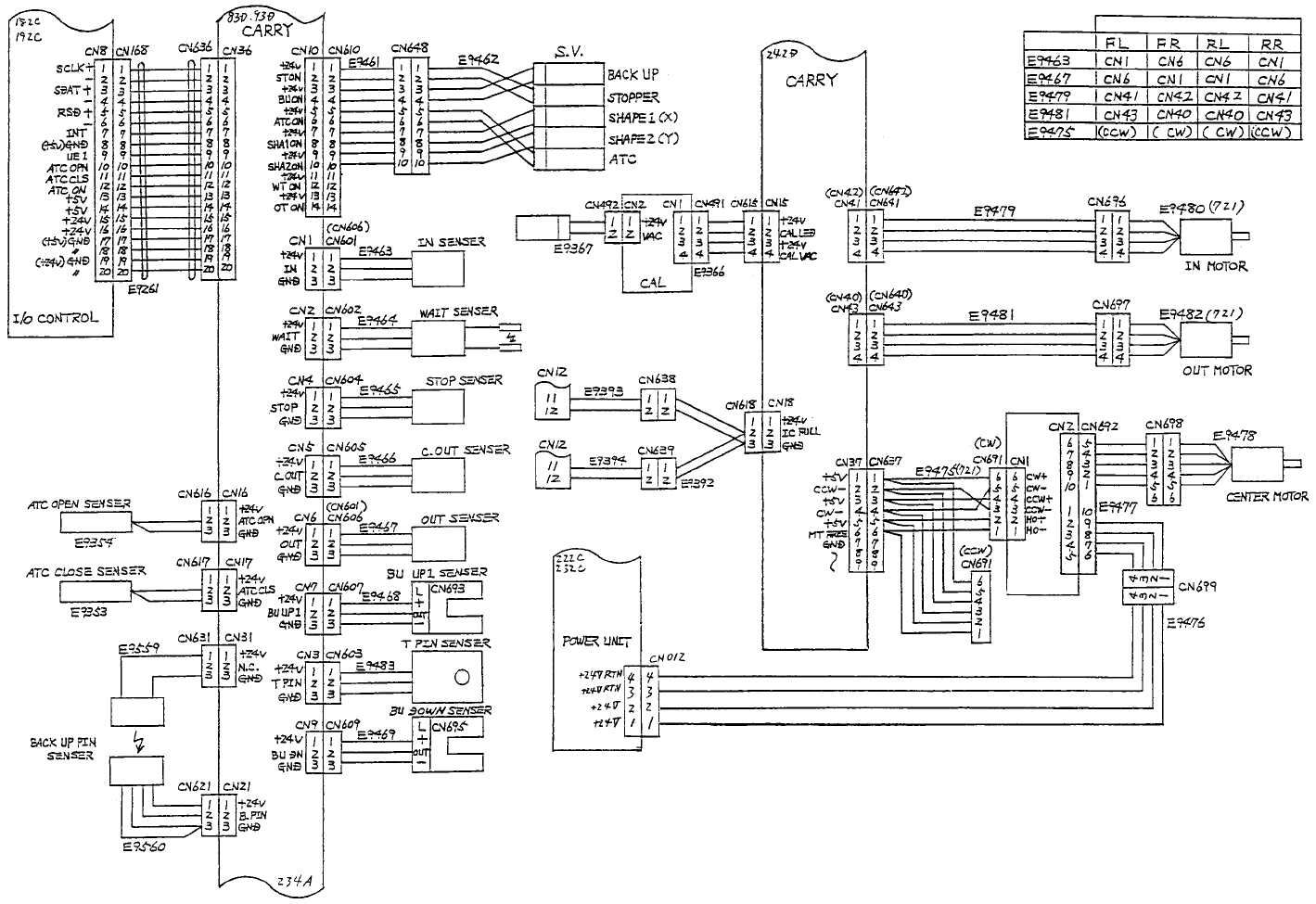
- 4 2 - (L3, Verification) KE-750,760 E9102725010 Main frame connection diagram BLACK BLACK Verify chuck S V Probe Range change relay output Verify probe Power supply unit
- 41 -
KE-750,760
E9102725010
Main frame connection diagram
WHITE
BROWN
GRAY
BLACK
WHITE
BROWN
GRAY
BLACK
BLUE
RED
ORANGE
GREEN
BLACK
BROWN
BLACK
BLUE
BROWN
BLACK
BLUE
BROWN
BLACK
BLUE
BROWN
BLACK
BLUE
BROWN
BLACK
BLUE
BROWN
BLACK
BLUE
GRAY/BLACK
G
RAY
GRAY/BLACK
GRAY
Calibration SV
(For connector bracket)
(For connector bracket)
5 dia.
driver
Connected to:
Cables
FL Front reference Left to Right
FR Front reference Right to Left
RL Rear reference Left to Right
RR Rear reference Right to Left
- 42 -
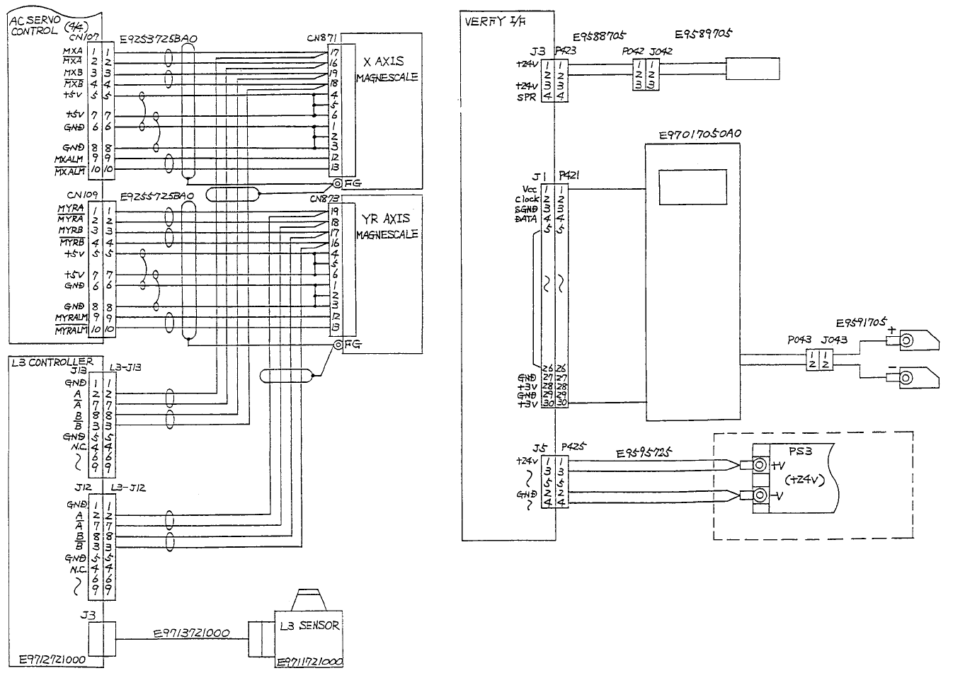
(L3, Verification)
KE-750,760
E9102725010
Main frame connection diagram
BLACK
BLACK
Verify chuck SV
Probe
Range change
relay output
Verify probe
Power supply unit

2. EXPLANATION ON XY, Z, AND θ AXES
2.1 Explanation on X/Y axes
Motor pulley M
Pulley XA
X (Y) belt Pulley XB
X motor (600 W)
Y motor (800 W)
• Deceleration ratio of motor pulley M to pulley XA: 36:120
• Ratio of diameter of the pitch circle of pulley XA: 28.65:114.59
The amount of movement of XY axes per motor rotation is:
36/120 × 28.65 × π = 27 mm
Therefore:
Resolution of motor encoder is 4096 (ppr) × 4 (multiplied) = 16,384 (ppr)
It is 27 mm/16,384 = 1.6479 µm/pulse
Resolution of linear scale is:
40 µm × 4 (multiplied) = 10 µm/pulse
Detection of open circuit of the external encoder
Every time the motor encoder rotates by 1/4 turn or every time the command
pulses equal to or more than 1/4 turn of the external encoder are input, an
alarm may occur if the difference between the rotation of the motor and the
rotation of the external encoder plus remaining pulses becomes 1/8 rotation of
the motor encoder or more.
A comparison and computation is carried out for 27/4 = 6.75 mm = 675 pulses
±675/2 pulses (1/8 rotation) at every 4096 pulses of 1/4 rotation.
- 43 -