KE-750_MAINTE.pdf - 第128页
6. DESCRIPTION OF SERVO MOTOR OPERATION (1) Control system of XY axes For KE series, a fully closed l oop system is sued to control the θ axis of the IC head, and also the XY axes. The following explains the theory of op…
- 124 -
Function of IMG-P board
① Reads and displays the images from the OCC camera and the VCS
camera.
② Obtains the center of gravity.
③ Performs computation for conventional image processing other than those
of template matching.
CCD camera
A (768 × 486)-element CCD is used, and (512 × 512) elements are used for
image processing.
5.2.6 Verification unit (optional)
See the separately supplied paper.
5.2.7 L.L.L (optional)
See the separately supplied paper.
6. DESCRIPTION OF SERVO MOTOR OPERATION
(1) Control system of XY axes
For KE series, a fully closed loop system is sued to control the θ axis of the
IC head, and also the XY axes. The following explains the theory of
operation.
AC servo control board
A
C servo drive
r
q + command
pulse
Power supply for the U, U, W phase drivers
Magnescale
Control
circuit
Memorizes
the current
position of
the
counter.
UP/DOWN
deviation
counter
- command pulse
Motor
w
Speed
detection
e
Magnet
detection
Rotary encoder
t Positioning pulse
Magnescale detector
r Position detection
Sensor head
XY axes
A
xis movement
direction
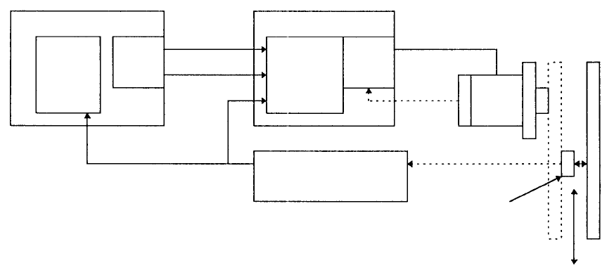
Figure 6.1 Fully closed loop system
Figure 6.1 shows the fully closed loop system of the XY axes. The example
below explains the operation where XY axes are moved by +100 mm from the
origin.
(1) The SUB CPU1 board of the control unit sets the data such as moving
distance, acceleration/deceleration, and maximum speed of the XY
axes to the AC servo control board, and issues a start command.
(2) At this step, both the counter of the AC servo board and the deviation
counter of the AC servo driver read zero. The profile is created on the
AC servo motor board using the data, and ① + command pulse
according to the acceleration is output to the servo driver.
(3) The number of the command pulses is read by the deviation counter of
the AC servo driver, and the power is supplied to the motor by the
control circuit to start the motor.
(4) The number of pulses from the rotary encoder is counted, the rotating
speed of the motor is detected (② speed detection), and the AC servo
driver controls (speed control) the motor so that it rotates at a constant
speed.
- 125 -
- 126 -
(5) When the XY axes move, the sensor head performs ③ magnet
detection (detects the magnetic material embedded every 40 µm) on
the magnescale, and moves. The ④ detection signal from the sensor
head is then multiplied by 4 at the magnescale detector (1 pulse = 10
µm), and the multiplied signal is fed back as ⑤ positioning pulse to
both the deviation counter of the AC servo driver and the counter of the
AC servo control board.
(6) The counter reading on the AC servo control board increases.
When the positioning pulse is input to the deviation counter of the AC
servo driver, the deviation counter performs a computation (Command
pulse minus positioning pulse). According to the counted value on the
deviation counter, the control circuit controls (positioning control) the
position of the XY axes. Therefore, when the XY axes approach the
target position which is 100 mm, the motor decelerates. When the XY
axes reach the position of 100 mm, the deviation counter value is set 0,
and the motor stops. Stop operation and acceleration/deceleration
operation differ depending on the gain setting of the AC servo driver.
So, an appropriate gain setting for the system shall be found and set.
When the (7) motor stops, the counter on the AC servo control board reads
100 mm/20 µm= 5000.
As described above, in the fully closed loop system, the speed control and
the positioning control are performed independently, and the position of the
XY axes is always detected with the magnescale, the axis can be stopped
accurately even if there is an over load or the belt becomes lose.
Using the fully closed loop system, a twin servo system of the Y axis can be
easily realized. In the twin servo system, two motors are simultaneously
driven. However, the characteristics of the servo driver and of the servo
motor are not the same between the YL axis and the YR axis. In addition,
the load conditions between the YL axis and the YR axis cannot be made
the same because of the difference in the position and installation of the
heads. Accordingly, there is a difference between the positions at the left
and the right even when the YL axis motor and the YR axis motor are
rotating.
In this case, in the fully closed loop system, the positions of the YL axis and
the YR axis are detected with the dedicated magnescale to each axis so
that an accurate positioning can be made.
On the other hand, in the semi-closed loop system (described on the next