KE-750_MAINTE.pdf - 第88页
3.7 Chip Rise Detection 3.7.1 Outline After picking the part, chip rise detecti on is performed immediately after the laser measurement which is started together with the movement of X/Y axes. For the chip rise detection…
Speed and acceleration for the θ axis to rotate for lazer measurement
Speed and acceleration for the θ axis to rotate for outside-lazer measurement
Low speed
50
385
20 5
279.9
Medium speed
93
1328
37 18
150.68
High speed
250
7500
100
63.25
Speed (Kpps)
Acceleration (Kpps
2
)
Speed ratio
(ratio % to high speed L: Speed, R: Acceleration)
Operating time (ms), Stroke 150 deg
KE-750/760
LAHD head
LA head
LAIC head
Low speed
150
7500
60 50
28.3
40
50
60
70
80
90
100
110
120
130
140
Medium speed
150
7500
60 50
28.3
40
50
60
70
80
90
100
110
120
130
140
High speed
250
15000
100
20
28.3
34.7
40.7
46.7
52.7
58.7
64.7
70.7
76.7
82.7
88.7
Speed (Kpps)
Acceleration (Kpps
2
)
Speed ratio
(ratio % to high speed L: Speed, R: Acceleration)
Operating time (ms) Stroke
Stroke
Stroke
Stroke
Stroke
Stroke
Stroke
Stroke
Stroke
Stroke
Stroke
Stroke
30
60
90
120
150
180
210
240
270
300
330
360
deg
deg
deg
deg
deg
deg
deg
deg
deg
deg
deg
deg
KE-750/760
LAHD head
LA head
LAIC head
Encoder:
2000 ppr
Resolution:
0.02 deg/pls
Speed and acceleration for the θ axis to rotate when centering is set for vision
Low speed
500
30000
100 50
28.3
40.7
52.7
64.7
76.6
88.7
100.7
112.7
124.7
136.7
148.7
160.7
Medium speed
500
30000
100 50
28.3
40.7
52.7
64.7
76.6
88.7
100.7
112.7
124.7
136.7
148.7
160.7
High speed
500
60000
100
20.3
32.3
44.3
56.3
68.3
80.3
92.3
104.3
116.3
128.3
140.3
152.3
Speed (Kpps)
Acceleration (Kpps
2
)
Speed ratio
(ratio % to high speed L: Speed, R: Acceleration)
Operating time (ms) Stroke
Stroke
Stroke
Stroke
Stroke
Stroke
Stroke
Stroke
Stroke
Stroke
Stroke
Stroke
30
60
90
120
150
180
210
240
270
300
330
360
deg
deg
deg
deg
deg
deg
deg
deg
deg
deg
deg
deg
KE-760
LAIC head
Encoder:
18000 ppr
Resolution:
0.005 deg/pls
Speed and acceleration for the Z axis to move down for part mount
Cover open
20
1200
206.6
Low speed
12.6
1260
20
311.5
Medium speed
25.2
2520
40
160.7
High speed
63
6300
100
70.3
Speed (Kpps)
Acceleration (Kpps
2
)
Speed ratio (ratio % to high speed)
Operating time (ms), Stroke 9.5 mm
KE-750
standard
machine
Cover open
20
1200
286.6
Low speed
18
1800
20
310
Medium speed
40.5
4050
45
143.3
High speed
90
9000
100
70
Speed (Kpps)
Acceleration (Kpps
2
)
Speed ratio (ratio % to high speed)
Operating time (ms), Stroke 13.5 mm
KE-760
standard
machine
Cover open
30
1500
333.3
Low speed
37.5
3750
25
260.7
Medium speed
90
9000
60
114.4
High speed
150
15000
50
72.6
Speed (Kpps)
Acceleration (Kpps
2
)
Speed ratio (ratio % to high speed)
Operating time (ms), Stroke 23.5 mm
KE-750
20-mm
application
machine
Cover open
30
1500
333.3
Low speed
37.5
3750
25
260.7
Medium speed
90
9000
60
114.4
High speed
150
15000
50
72.6
Speed (Kpps)
Acceleration (Kpps
2
)
Speed ratio (ratio % to high speed)
Operating time (ms), Stroke 23.5 mm
KE-760
20-mm
application
machine
Speed and acceleration for the Z axis to move up for part mount
Cover open
20
1200
372.6
Low speed
60
3000
20 10
120.7
Medium speed
120
6000
40 20
79.3
High speed
300
30000
100
33.7
Speed (Kpps)
Acceleration (Kpps
2
)
Speed ratio
(ratio % to high speed L: Speed, R: Acceleration)
Operating time (ms), Stroke 17.8 mm
KE-750
standard
machine
Cover open
20
1200
482.7
Low speed
60
3000
20 10
175.3
Medium speed
135
6750
45 23
89
High speed
300
30000
100
41.1
Speed (Kpps)
Acceleration (Kpps
2
)
Speed ratio
(ratio % to high speed L: speed, R: acceleration)
Operating time (ms), Stroke 23.3 mm
KE-760
standard
machine
Cover open
30
1500
10 5
444
Low speed
60
3000
20 10
232
Medium speed
120
6000
40 20
126
High speed
300
30000
100
52.4
Speed (Kpps)
Acceleration (Kpps
2
)
Speed ratio
(ratio % to high speed L: speed, R: acceleration)
Operating time (ms), Stroke 31.8 mm
KE-750
20-mm
application
machine
Cover open
30
1500
10 5
470.1
Low speed
60
3000
20 10
245.3
Medium speed
135
6750
45 23
120.1
High speed
300
30000
100
55.1
Speed (Kpps)
Acceleration (Kpps
2
)
Speed ratio
(ratio % to high speed L: speed, R: acceleration)
Operating time (ms), Stroke 33.8 mm
KE-760
20-mm
application
machine
- 84 -
3.7 Chip Rise Detection
3.7.1 Outline
After picking the part, chip rise detection is performed immediately after the
laser measurement which is started together with the movement of X/Y axes.
For the chip rise detection, the Z axis is moved to the height obtained from the
thickness of the part being picked, and whether the part is picked is scanned
with the laser. Whether to perform the chip rise detection can be set using the
part data or the setup data. When the chip rise detection is performed, there
may be a delay in the cycle time depending on the distance of the X/Y
movement or the method of pick.
3.7.2 Detection
Chip rise detection is mainly applied to square chip parts and Melf parts.
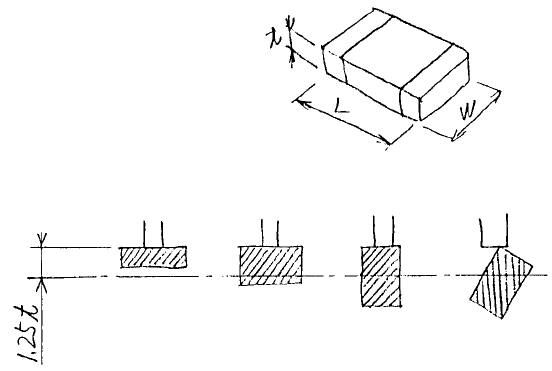
Scanning for detection is performed by adjusting the laser height using the
value which is the part thickness t entered as the part data multiplied by a
constant 1.25.
Part size
Horizontal
rise
Normal pick Vertical rise Slant rise
Laser height
When part pick is performed normally, Status 64 (No Component) is returned as
data. When a chip rise occurs, the laser is obstructed with the part, and a
status other than 64 is returned. In this case, the part is rejected being
detected as chip rise.
- 85 -
The constant 1.25 is obtained as follows:
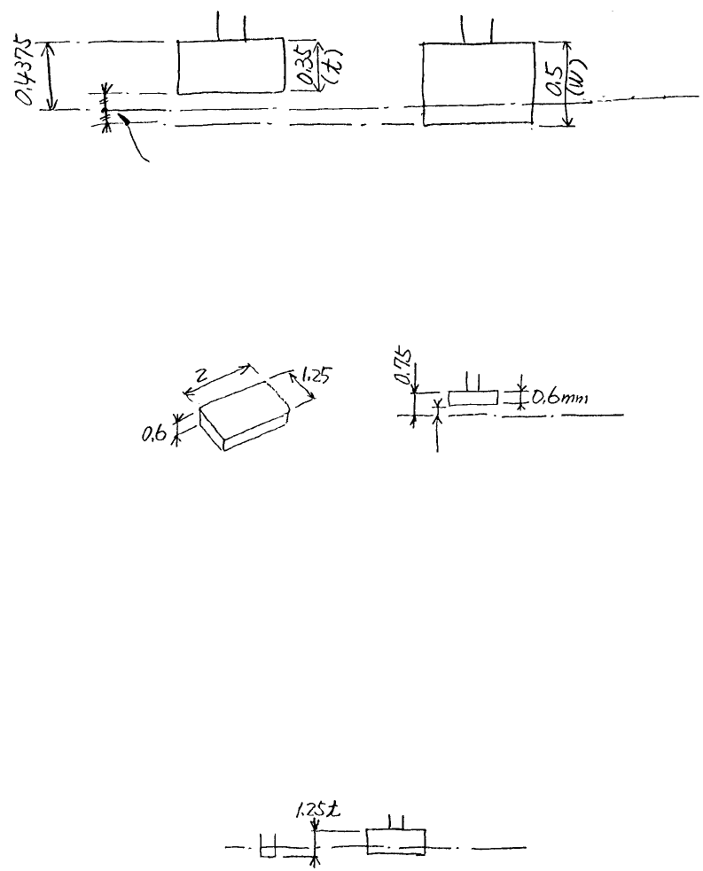
The size of a 1005 type resistor is t = 0.35 mm and W = 0.5 mm. So, the
height for horizontal rise detection is about 1.25 × t when the middle of the
space shown in the figure below is scanned.
(0.35 + 0.5)/2≒1.25 × 0.35
where: t is 0.35, and W is 0.5.
Normal pick
Horizontal
rise pick
Laser scanning height
Scanning at the middle of the space
(1) If the entered value of the part height is different from the actual part
dimensions, the part will be rejected even when it is normally picked. For
2125R type, t = 0.6 mm, and scanning height for the chip rise is 0.6 × 1.25
= 0.75.
Laser scanning height
0.15 mm (Space)
If an incorrect value of 0.4 mm has been entered for the part height, the
scanning height is 0.5 mm (0.4 × 1.25), and the part will be rejected even
when pick is performed normally. In this case, measure the part height
by automatic measurement, and enter the correct value.
(2) If the laser height of the nozzle is incorrect, the part will be rejected even
when pick is performed normally. If the laser height of the nozzle (Set-up
data) is set below the correct position, the chip normally picked will be
detected at the laser scanning height.
Laser scanning height
- 86 -
The laser height of the
nozzle is set too low.
Even when the nozzle moved up by 1.25 t,
the chip will be detected by the laser