KE-750_MAINTE.pdf - 第171页
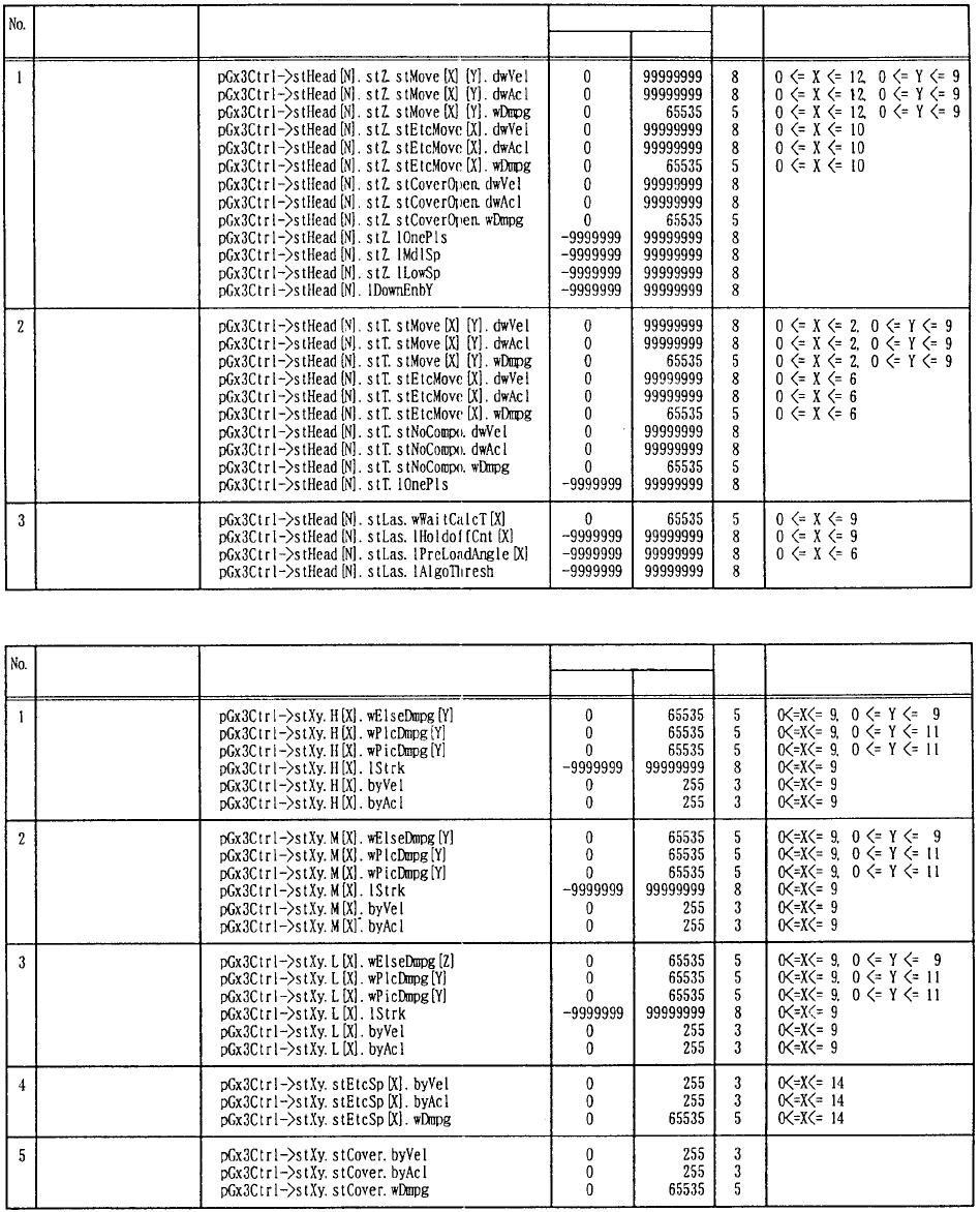
5. SETTING VALUES' RANGE OF MECHANISM CONTROL PARAMETERS (TABLE 1) (1) Head N (0<=N<=5) No. of arrays Item No. of digits Setting range Minimum value Maximum value Z axis θ axis Laser (2) XY axes No. of digits …
- 29 -
4.4 Printing
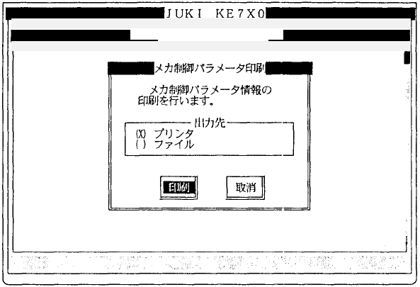
Selecting [2/Printing] from [3/Printing] displays the dialog below for printing.
(1) Output destination
• Using the radio button, select the output destination of parameter
information.
The default setting of the radio button is made by the "Target" setting of
the printing environment file (PRINTER.INI).
q Printer
w File
File name: CTRL.TXT0
Path name: Path (cStart_Dir[]) where the execution file (Extension is
EXE) of man-machine is stored.
Mechanical control parameter
1/File 2/Data in
p
ut 3/Prod. 4/Setu
p
5/Mainte. 6/Print 7/Others
1/In
p
ut 2/Dis
p
la
y
3/Print 9/Exit
5. SETTING VALUES' RANGE OF MECHANISM
CONTROL PARAMETERS (TABLE 1)
(1) Head N (0<=N<=5)
No. of arrays
Item
No.
of
digits
Setting range
Minimum
value
Maximum
value
Z axis
θ axis
Laser
(2) XY axes
No.
of
digits
No. of arrays
Item
Setting range
Minimum
value
Maximum
value
High speed for PTP
operation
Medium speed for
PTP operation
Low speed for PTP
operation
Others
When cover is open
- 30 -
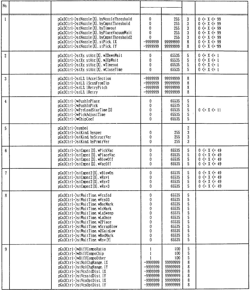
(3) Others
No.
of
digits
Item
No. of arrays
Setting range
Maximum
value
Minimum
value
Nozzle information
A
TC
Laser read locator
Others
Version information
Vacuum waiting time
(ms) per part type
Vacuum waiting time
2 (ms) per part type
Other waiting times
(ms)
Others 2
- 31 -