KE-750_MAINTE.pdf - 第76页
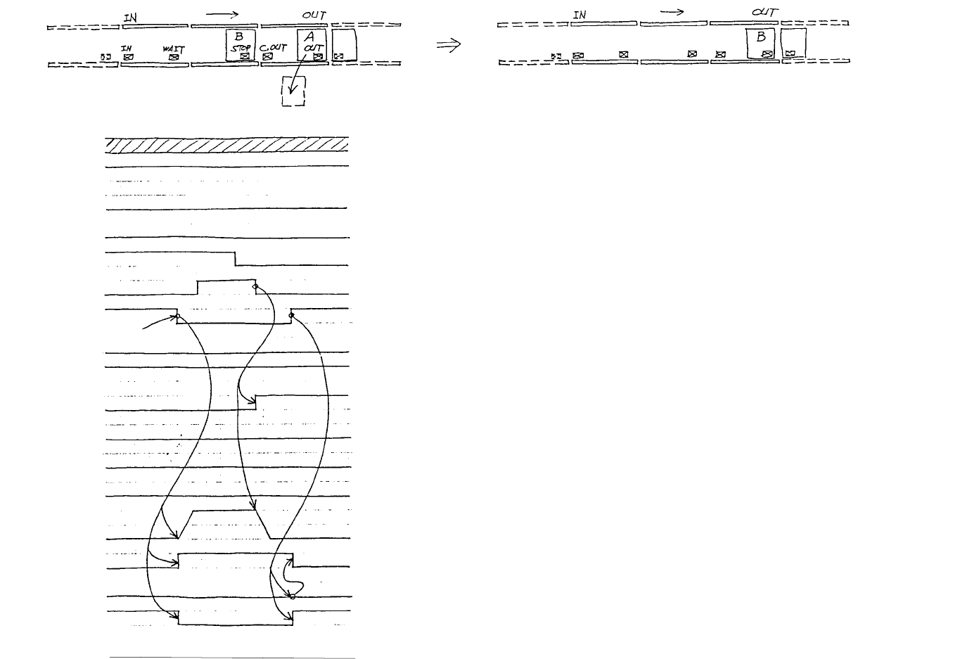
- 7 3 - (21) This chart shows that board A on the OUT sensor waiting to b e carried out i s removed. This chart shows that board A i s returned between C.OUT sensor and the OUT sensor. B.A.IN Ready OUT I N sensor WAIT se…
- 72 -
(20)
This chart shows that production of
board B has been completed, waiting for
board A to be carried out.
[Key operation]
There is no latch operation of "board loaded" condition for the OUT buffer
though it is available with the IN buffer. Therefore, when the board on the
OUT sensor is moved out, the next board can be carried in, disregarding the
board carriage completion by turning the motor. Because the OUT sensor
can be installed in a wide range of position, it is noted in the operation manual
to adjust the sensor position for the board which has slits.
Manually remove.
B.A.IN
Ready OUT
IN sensor
WAIT sensor
STOP sensor
C.OUT sensor
OUT sensor
BU UP sensor
BU DN sensor
Stopper
Backup
External shape
cramp 1 (X)
IN motor
CENT motor
OUT motor
Ready IN
B.A.OUT
External shape
cramp 2 (Y)
Remove board A which is waiting
to be carried out by hand.
- 73 -
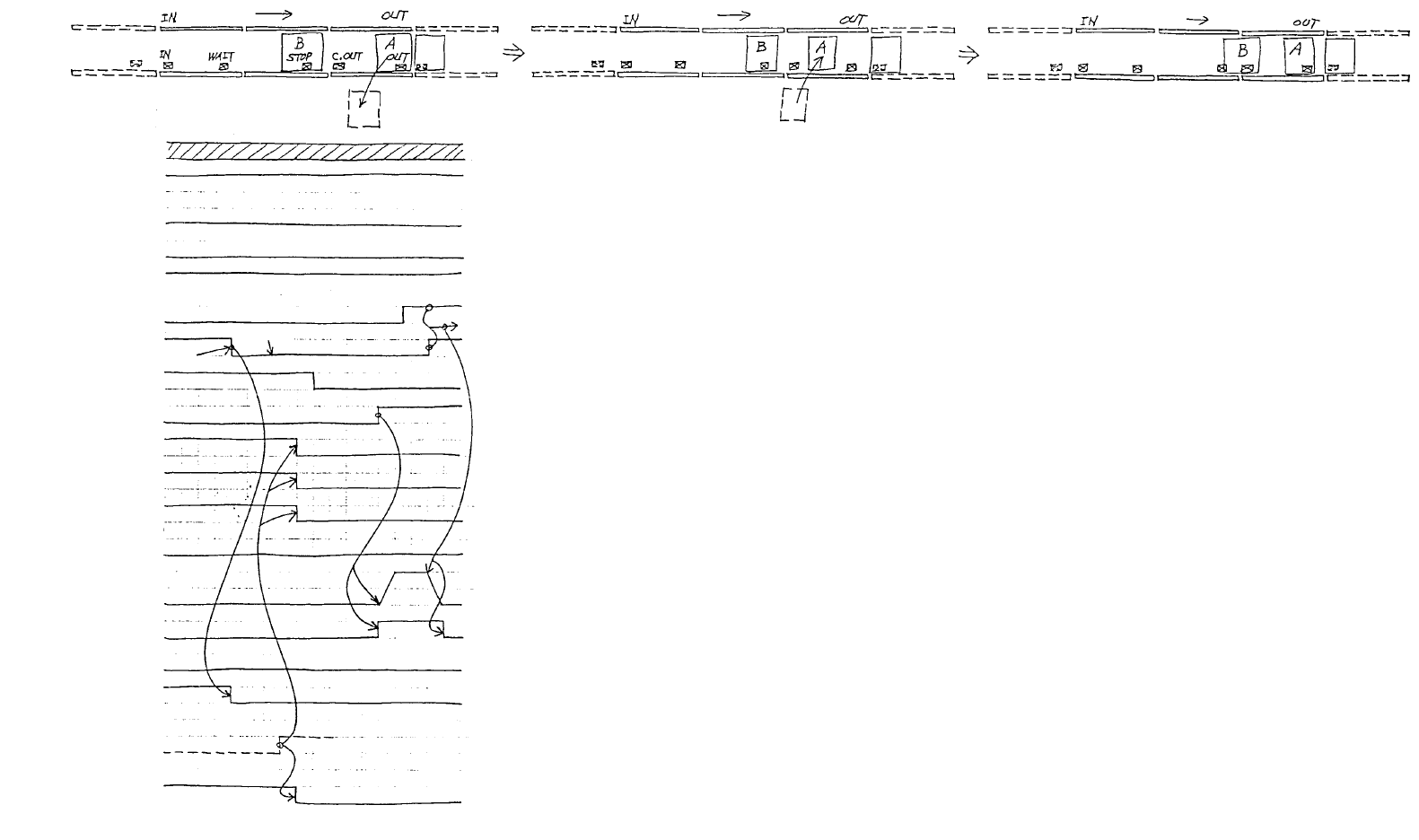
(21)
This chart shows that board A on the OUT
sensor waiting to be carried out is removed.
This chart shows that board A is returned
between C.OUT sensor and the OUT sensor.
B.A.IN
Ready OUT
IN sensor
WAIT sensor
STOP sensor
C.OUT sensor
OUT sensor
BU UP sensor
BU DN sensor
Stopper
Backup
External shape
cramp 1 (X)
IN motor
CENT motor
OUT motor
Ready IN
B.A.OUT
Continuous
production (Carriage
start)
External shape
cramp 2 (Y)
Manually
remove.
Returned.
OUT buffer error
[Key operation]
When the OUT sensor does not detect a board, the OUT buffer is se
for carriage in possible condition. The chart on the left shows an
error status. But, this error does not always occur when a board
which is short in X direction is placed close to the C.OUT sensor.
- 74 -
3.3 Nozzle Replacement
3.3.1 Z axis speed and crosstalk for nozzle replacement
The speed profile of Z axis shall be the same for LAHD, LA, and LAIC head.
Maximum speed: 250 kpps
Acceleration: 15000 kpps
2
(For lift down/up for replacement: 3800 kpps
2
)
Standby position
Lift up for nozzle YES/NO check
Laser height
Lift down to standby position
Standby position
Lift down to nozzle replacement height
Replacement height
Lift up for replacement fault check
Laser height
Lift down to standby position
Standby position
9
›8
17
fl8
9
fl36.9
-27.9
›44.9
17
fl8
9
29.2
29.2
124.6
137.6
29.2
13
›10.3
23.3
fl10.3
13
23.3
fl10.3
13
33.1
33.1
33.1
fl40.9
-27.9
›51.2
fl39.9
-26.9
›50.2
132.1
147.7
129.6
146.1
Nozzle height
form the top
surface of
board (mm)
Transport time
(ms)
Nozzle height
form the top
surface of
board (mm)
Transport time
(ms)
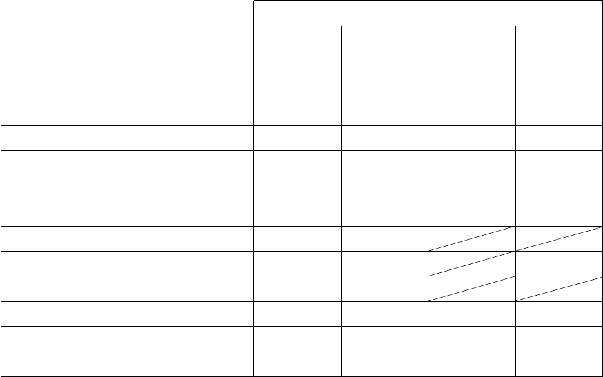
KE-730 KE-740
NOTE:
Top/bottom line in the box of the table means:
Top: For the nozzle served to only the laser
Bottom: For the nozzle served to the vision and
the laser (vision/laser)
NOTE:
Replacement height differs between the nozzle of KE740 dedicated to the laser
and the vision/lazer nozzle with black urethane rubber. (The vision/lazer
nozzle is higher by 1 mm than the the nozzle dedicated to the lazer.) Nozzle
location No. for the vision/laser nozzle is W, X, Y, and Z.