KE-750_MAINTE.pdf - 第90页
In this case, obtain the laser s ensor height of each head in the maintenance mode, and reinstall the nozzl e height by nozzle allocation of the Set-up data. (3) The part may be rejected depending on t he pick condition.…
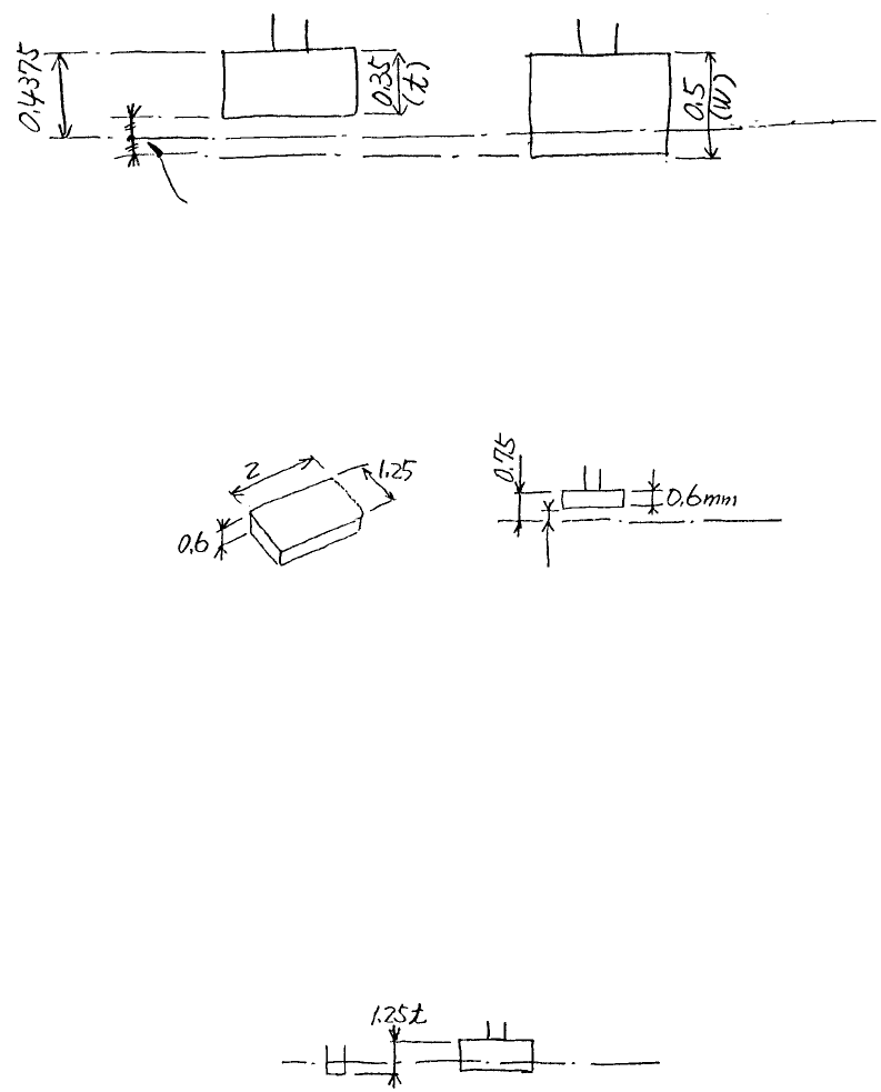
The constant 1.25 is obtained as follows:
The size of a 1005 type resistor is t = 0.35 mm and W = 0.5 mm. So, the
height for horizontal rise detection is about 1.25 × t when the middle of the
space shown in the figure below is scanned.
(0.35 + 0.5)/2≒1.25 × 0.35
where: t is 0.35, and W is 0.5.
Normal pick
Horizontal
rise pick
Laser scanning height
Scanning at the middle of the space
(1) If the entered value of the part height is different from the actual part
dimensions, the part will be rejected even when it is normally picked. For
2125R type, t = 0.6 mm, and scanning height for the chip rise is 0.6 × 1.25
= 0.75.
Laser scanning height
0.15 mm (Space)
If an incorrect value of 0.4 mm has been entered for the part height, the
scanning height is 0.5 mm (0.4 × 1.25), and the part will be rejected even
when pick is performed normally. In this case, measure the part height
by automatic measurement, and enter the correct value.
(2) If the laser height of the nozzle is incorrect, the part will be rejected even
when pick is performed normally. If the laser height of the nozzle (Set-up
data) is set below the correct position, the chip normally picked will be
detected at the laser scanning height.
Laser scanning height
- 86 -
The laser height of the
nozzle is set too low.
Even when the nozzle moved up by 1.25 t,
the chip will be detected by the laser
In this case, obtain the laser sensor height of each head in the
maintenance mode, and reinstall the nozzle height by nozzle allocation of
the Set-up data.
(3) The part may be rejected depending on the pick condition. For example,
for the 2125R type, the space between the bottom surface of the part and
the scanning height is 0.15 mm, and if the part is picked inclined, it may be
rejected.
Scanning height
In this case, there is a problem with the pick position, and it shall be
reviewed. Because the setting value for the height of the chip rise
detection can be changed with the part data of each part, a safer setting
can be made for some part size.
Normal pick Horizontal rise pick
Laser scanning
height
Scanning at the middle of the space
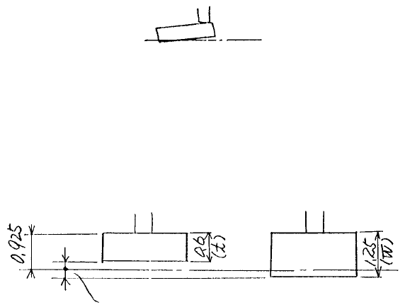
The default value obtained with the above part size is 1.25 × t = 0.75 mm.
However, when the laser height is set at the middle of the space between
the normal pick position and the horizontal rise pick position, it it (t + W)/2
= (0.6 + 1.25)/2 = 0.925 mm. Accordingly, if this part is rejected when
picked, it is effective to change the detection height to 0.925 mm.
Note that how to obtain (t + W)/2 cannot be applied to all types of parts.
For the parts which are of the same thickness (t) and width (W) (e.g.
1608C and 1005C), (t + W)/2 = t applies, and they can be rejected even
when normally picked.
(For 1608C, T = 0.8 mm and W = 0.8 mm.
Therefore, chip rise detection height H = (0.8 + 0.8)/2 = 0.8 mm.)
- 87 -
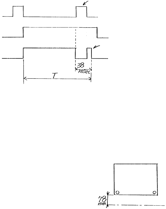
3.7.3 Timing detection and tact time of chip rise detection
During production, chip rise detection is performed at the timing after
measurement result is obtained. The measurement result is obtained after
completing the part pick and performing the laser measurement at the same
time as starting of the X/Y axes movement.
- 88 -
Moves to the scanning height after
LA measurement
Moves upward after pick
Z axis
X-Y
LA measurement
Moves to the mount position
Laser measurement
Chip rise scanning
For the chip rise detection, it takes 38 ms including the time for the Z axis to
move upwards and for the scanning. Therefore, if the distance between the
pick position and the mount position is more than 80 mm, the time for the X-Y
movement becomes longer than time T for the laser measurement and chip rise
detection, and tact time is not extended because the chip rise detection is
included in the X-Y movement.
The minimum distance from the pick point to the
edge of the board is 78 mm, and tact time can
becomes longer only when mounting is made in
the range between 78 mm and 80 mm.
Board
In this case, the tact down time delays:
Pick point
38 ms/chip for 1-head mount,
38/2 = 19 ms/chip for simultaneous 2-head
pick, and
K The minimum distance
between the rear pick
point at the rear fiducial is
also 78 mm.
38/3 = 12.6 ms for simultaneous 3-head
pick.
NOTE:
For alternating pick by 2- to 3-head type, there is no tact time delay because
after the component is picked with the 1st pick head, the laser measurement
and the chip rise detection are performed, and during this time, the component
is picked with the 2nd pick head.