KE-750_MAINTE.pdf - 第85页
KE-760 Picture Recognition Mount No. Drive axis Operation ① XY Moves from the mount position to the pick position. ② RZ Moves down from the top standby position to the pick height for part pick. ③ RZ After picking the pa…
⑫
XY
Moves by adding the offset of ΔX and ΔY which is the result of the laser
measurement of the R head. After movement is complete, vacuum check is
performed to detect whether or not the part is picked. If no part status is
detected, the Z axis is moved up. Then, the part is adjusted to the laser
height, and check is performed again by Measure Once command using laser.
If no part status is detected again, the part is discharged and re-pick is
performed.
⑯
RZ After stopping X and Y, the R head moves down immediately for mounting.
⑰
RZ The R head moves from the mount height to the standby position at the top.
⑱
XY Moves from the mount position to the pick position.
⑲
Lθ, Rθ While X and Y are moving, returns each θ axis from the mount angle to 0°.
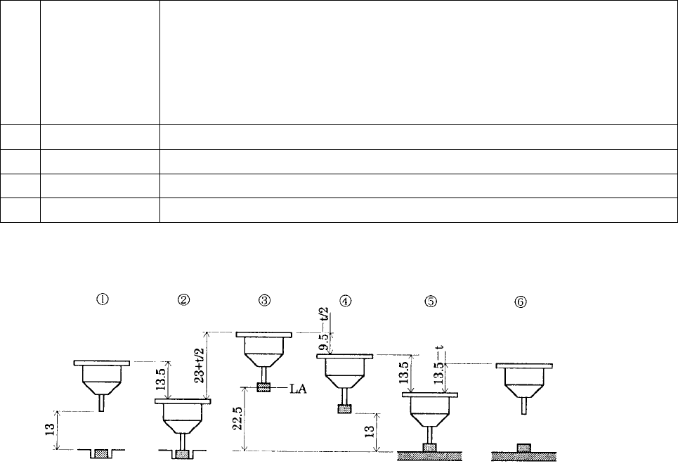
The figure below shows the production operation sequence. t in the figure is thickness of the
element.
Top surface of
the board
① First, at the pick position, the distance between the tip of the nozzle and the surface of the board
(the same as the top surface of the part to be picked) is 13 mm.
② Moves down by 13.5 mm to pick the part (13 mm + 0.5 mm of pushing amount which is a default
value and changeable as part data).
③ Moves up by (23 + t/2) mm so that the center (middle level) of the part is placed at the same level
as the laser surface which is 22.5 mm. This movement is a default setting, and it can be
changed as part data.
④ After measured by LA, moves down by (9.5 - t/2) mm so that the bottom tip of the part is set at 13
mm height.
⑤ Moves down by 13.5 mm which is the distance between the top surface of the board and the
bottom tip of the part, plus 0.5 mm (default value) which is nozzle pushing amount.
⑥ Moves up by (13.5 - t) mm so that the bottom tip of the nozzle is set 13 mm above the top
surface of the board.
- 81 -
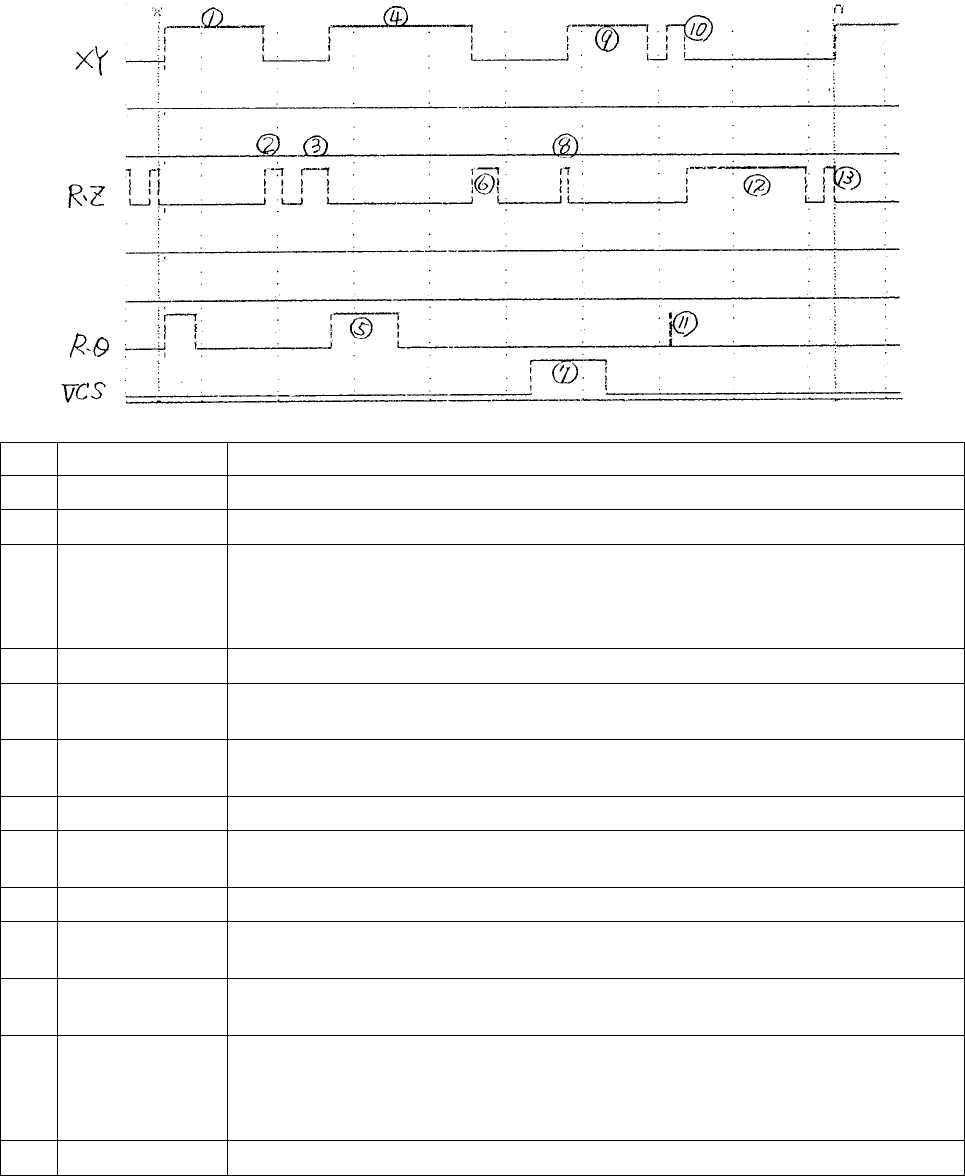
KE-760 Picture Recognition Mount
No. Drive axis Operation
①
XY Moves from the mount position to the pick position.
②
RZ Moves down from the top standby position to the pick height for part pick.
③
RZ After picking the part, moves the bottom surface of the part up to the standby
position at the top. After moved up, vacuum check is performed to detect
whether the part is set. If no part status is detected, re-pick is performed with
the number of retries specified for part data.
④
XY Moves the R head from the pick position to the vision recognition camera.
⑤
Rθ
At the same time when the X and Y axes start to move, rotate for the mount
angle.
⑥
RZ After the movement of the vision recognition camera is complete, the Z axis is
moved down so that the bottom tip of the part is set at the recognition height.
⑦
VCS Picture recognition and computation are performed.
⑧
RZ After vision recognition, the Z axis is moved up so that the bottom tip of the part
is moved from the recognition height to the standby position at the top.
⑨
XY After vision recognition, moves to the theoretical coordinate for the mount.
⑩
XY
After moving to the theoretical coordinate, moves by the offset of ΔX and ΔY
which is the result of the vision recognition computation. (Correction)
⑪
Rθ Rotates by the offset of Δθ which is the result of the vision recognition
computation.
⑫
RZ
After correcting X, Y, and θ, moves down for mount. Immediately before
moving down, vacuum check is performed to detect whether or not the part is
picked. If no part status is detected, the part is discharged and re-pick is
performed.
⑬
RZ The R head moves from the mount height to the standby position at the top.
- 82 -
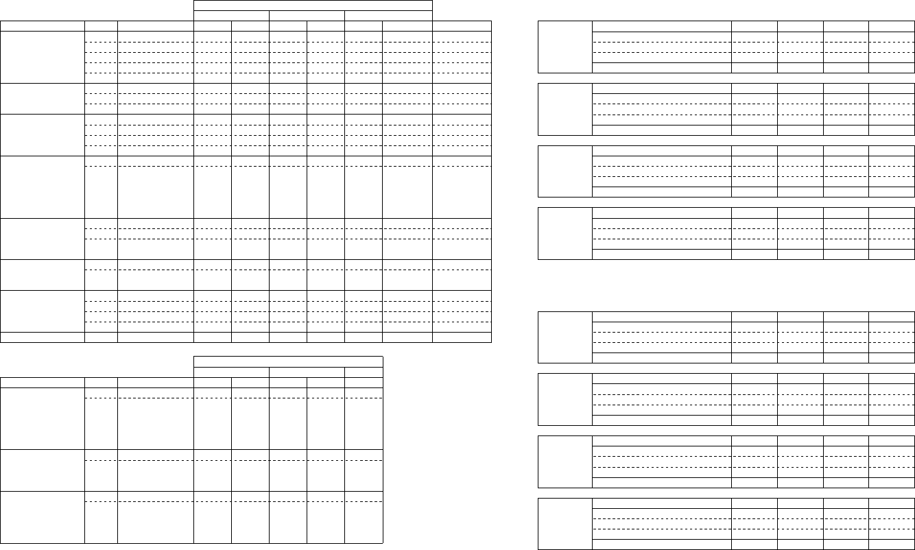
3.6 Z/θ operation classification, speed, and acceleration by part types
Typical partDown Up Down Up
Measurement
Outside-measurement
Type No.
Part type
Minimum part width (W)
1005
1608
2125 3216
ss mini, s mini
SOT23
Square chip
network resistor
Melf
SOT
PLCC
SOJ
J-lead socket
Gull-wing socket
Socket with bumper
One-way lead connector
SOP
TSOP
HSOP
Two-way lead connector
QFP
BGA
BQFP
Aluminum electrolytic capacitor
Tantalum capacitor
Trimmer capacitor
GaAsFET
Others
TYPE 1
TYPE 0
TYPE 0
TYPE 2
TYPE 9
TYPE 0
TYPE 2
TYPE 9
TYPE 0
TYPE 0
TYPE 2
TYPE 9
TYPE 4
TYPE 3
TYPE 4
TYPE 5
TYPE 0
TYPE 2
TYPE 9
TYPE 9
0.5≦W<0.8
0.8≦W<1.25
1.25≦W<2.5
2.5≦W<20
20≦W<50
0.5≦W<2.5
2.5≦W<20
20≦W<50
0.5≦W<1.25
1.25≦W<2.5
2.5≦W<20
20≦W<50
0.5≦W<50
0.5≦W<5
5≦W<50
0.5≦W<50
0.5≦W<3.2
3.2≦W<33.5
33.5≦W
<50
0.5≦W<50
Medium speed
Medium speed
High speed
High speed
High speed
High speed
High speed
High speed
Medium speed
High speed
High speed
High speed
High speed
High speed
High speed
High speed
High speed
High speed
High speed
High speed
High speed
High speed
High speed
High speed
High speed
High speed
High speed
High speed
High speed
High speed
High speed
High speed
High speed
High speed
High speed
High speed
High speed
High speed
High speed
High speed
High speed
High speed
High speed
High speed
High speed
High speed
High speed
High speed
High speed
High speed
High speed
High speed
Medium speed
Medium speed
Medium speed
Medium speed
High speed
High speed
High speed
High speed
High speed
High speed
High speed
High speed
High speed
Medium speed
Medium speed
Medium speed
Medium speed
Medium speed
Medium speed
Medium speed
High speed
High speed
High speed
High speed
Medium speed
Medium speed
Medium speed
High speed
High speed
High speed
High speed
High speed
High speed
High speed
High speed
High speed
High speed
High speed
High speed
High speed
Low speed
Medium speed
Low speed
Low speed
High speed
High speed
High speed
Low speed
High speed
High speed
High speed
High speed
Low speed
High speed
High speed
Low speed
High speed
High speed
High speed
Low speed
Medium speed
Medium speed
Medium speed
Medium speed
High speed
High speed
Low speed
High speed
Z axis at pick Z axis at mount
Speed classification of Z and θ axes
θ axis
Speed classification of the Z and θ axes
when centering is set for laser
Down Up Down Up
Type No.
Part type
Minimum part width (W)
PLCC
SOJ
J-lead socket
Gull-wing socket
Socket with bumper
One-way lead connector
SOP
TSOP
HSOP
Two-way lead connector
QFP
BGA
BQFP
GaAsFET
Aluminum electrolytic capacitor
TYPE 7
TYPE 6
TYPE 7
W≦50
W≦50
W≦50
High speed
High speed
High speed
High speed
High speed
High speed
Medium speed
Low speed
Low speed
High speed
High speed
Medium speed
Medium speed
Medium speed
Medium speed
Z axis at pick Z axis at mount
Speed classification of Z and θ axes
θ axis
Speed classification of the Z and θ axes
when centering is set for vision
NOTE 1: For the speed of the Z axis to move up for pick, the speed is changed to medium when the part size exceeds 8 × 8 mm.
NOTE 2: For the θ speed outside-measurement, including vision recognition, the speed is changed to low when the part size exceeds 20 × 20 mm.
Speed and acceleration for the Z axis to move down for part pick
Cover open
20
1200
206.6
Low speed
37.2
3720
20
112.1
Medium speed
74.4
7440
40
61
High speed
186
18600
100
30.4
Speed (Kpps)
Acceleration (Kpps
2
)
Speed ratio (ratio % to high speed)
Operating time (ms), Stroke 9.5 mm
KE-750
standard
machine
Cover open
20
1200
286.6
Low speed
43.2
4320
20
135
Medium speed
97.2
9720
45
65.5
High speed
216
21600
100
35
Speed (Kpps)
Acceleration (Kpps
2
)
Speed ratio (ratio % to high speed)
Operating time (ms), Stroke 13.5 mm
KE-760
standard
machine
Cover open
30
1500
333.3
Low speed
75
7500
25
135.3
Medium speed
180
18000
60
62.2
High speed
300
30000
100
41.3
Speed (Kpps)
Acceleration (Kpps
2
)
Speed ratio (ratio % to high speed)
Operating time (ms), Stroke 23.5 mm
KE-750
20-mm
application
machine
Cover open
30
1500
333.3
Low speed
75
7500
25
135.3
Medium speed
180
18000
60
62.2
High speed
300
30000
100
41.3
Speed (Kpps)
Acceleration (Kpps
2
)
Speed ratio (ratio % to high speed)
Operating time (ms), Stroke 23.5 mm
KE-760
20-mm
application
machine
Speed and acceleration for the Z axis to move up for part pick
Cover open
20
1200
372.6
Low speed
60
6000
20
128.6
Medium speed
120
12000
40
69.3
High speed
300
30000
100
33.7
Speed (Kpps)
Acceleration (Kpps
2
)
Speed ratio (ratio % to high speed)
Operating time (ms), Stroke 17.8 mm
KE-750
standard
machine
Cover open
20
1200
482.7
Low speed
60
6000
20
165.3
Medium speed
135
13500
45
79
High speed
300
30000
100
41.1
Speed (Kpps)
Acceleration (Kpps
2
)
Speed ratio (ratio % to high speed)
Operating time (ms), Stroke 23.3 mm
KE-760
standard
machine
Cover open
30
1500
444
Low speed
75
7500
25
179.6
Medium speed
180
18000
60
80.6
High speed
300
30000
100
52.4
Speed (Kpps)
Acceleration (Kpps
2
)
Speed ratio (ratio % to high speed)
Operating time (ms), Stroke 31.8 mm
KE-750
20-mm
application
machine
Cover open
30
1500
470.6
Low speed
75
7500
25
190.3
Medium speed
180
18000
60
85.1
High speed
300
30000
100
55.1
Speed (Kpps)
Acceleration (Kpps
2
)
Speed ratio (ratio % to high speed)
Operating time (ms), Stroke 33.8 mm
KE-760
20-mm
application
machine
Speed classification of the Z and θ axes of KE-750/760
- 83 -