KE-750_MAINTE.pdf - 第5页
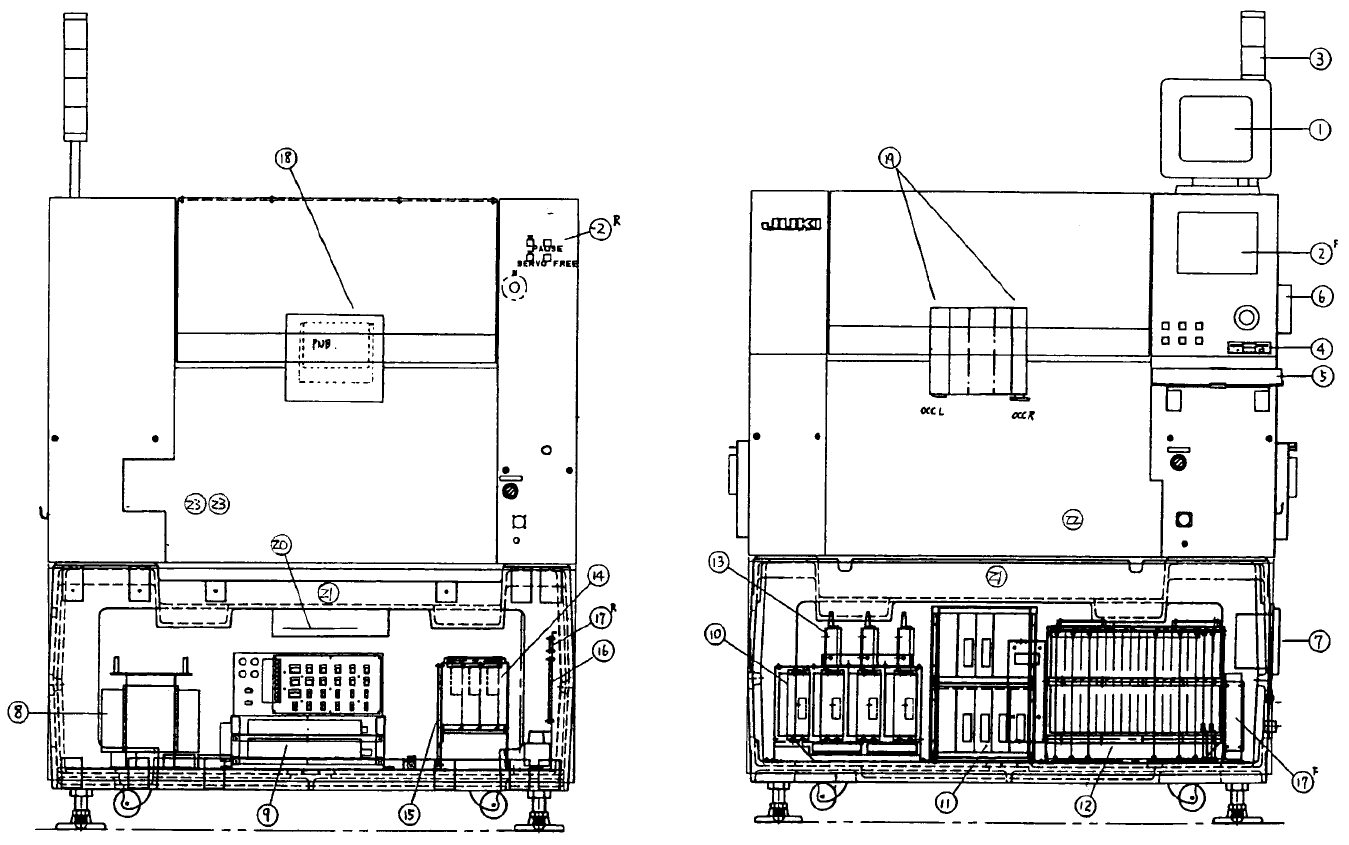
- 2 - Figure 1.1.2 Rear view Figure 1.1.1 Front view

1. BLOCK DIAGRAM
1.1 Layout of Electric Section
Figure 1.1.1 shows the front view, and Figure 1.1.2 shows the rear view of the
electric section.
Name of Parts
① Picture monitor
② Panel computer
[Front: Arcnet board assembly, operation board assembly, operation SW
board assembly, HDD]
[Rear: Operation SW board A assembly]
③ Signal light (Beacon)
④ FDD
⑤ Keyboard
⑥ HOD
⑦ Power switch
⑧ Power transformer
⑨ Power supply unit
⑩ AC servo driver for X/Y axes
⑪ AC servo driver for Z/θ axes
⑫ Control unit
[SUB CPU board assembly, AC servo control board assembly, Z/θ control
board assembly, I/O control board assembly, MATCHING board assembly,
IMG-P board assembly, Optional: L.L.L PWB verification board assembly]
⑬ Magnescale detector
⑭ LA/LAHD unit
⑮ Base unit (Board assembly)
⑯ Feeder unit (Board assembly)
⑰ Feeder I/F (Board assembly) [Front and rear]
⑱ Head unit
[Head main board assembly, head motor board assembly, Optional: HMS,
Bad mark sensor]
⑲ OCC camera and light (Board assembly) [Left and right]
⑳ Carry (Board assembly)
Feeder bank (Board assembly)
21
CAL block (Board assembly)
22
VCS camera and light (Board assembly) (0.4, 0.3, BGA, CSP)
23
- 1 -
- 2 -
Figure 1.1.2 Rear view Figure 1.1.1 Front view
- 3 -
KE-750
E9101725010
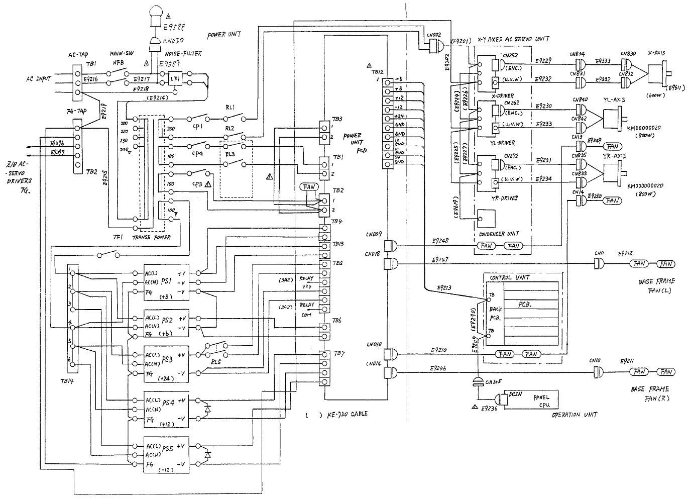
Main frame diagram