KE-750_MAINTE.pdf - 第127页
- 124 - Function of IMG-P board ① Reads and displays the images from the OCC camera and the VCS camera. ② Obtains the center of gravity. ③ Performs computation for conventional image processing other than those of templa…
- 123 -
(3) Base unit board (Base unit)
① Turns on and off the OCC and BOC lights (W).
② Turns on and off the VCS, BGA, and CSP (optional) lights (KE-760).
③ Turns on and off, and flashes the beacon lamp (W).
④ Monitors the source pressure level, and performs the interrupt
processing (INT).
⑤ Detects the feeder rise status (R).
⑥ Supplies +6/24 VDC power to each option feeder.
(4) Feeder unit board (Feeder unit)
① Independently drives the solenoid of the feeder knock pins (80 pins)
(W).
② Reads Ready/Busy signals of the stacked stick feeder (optional) (R).
③ Disables the stick feeder of 32-mm adhesive type (optional) (W).
The signal of item ① is parallel data. However, the signals of items ② and
③ are converted to 16-bit serial data on the feeder I/F boards each installed in
the main unit and in the bank.
(5) Operation board
① Reads the status (start, stop, etc.) of the switches on the operation
switch board installed at the front and back of the cover (R), and turns
on and off the LEDs (ORIGIN, servo free) (W).
② Read the status of each key on the HOD (R), and turns on and off the
LEDs (W).
③ Notifies the status of the cover open switch, the servo free switch, and
the emergency stop switch to the AC servo control board.
(6) Interface to external equipment
① Interface for the MTC.
② Interface for SMEMA (Ready IN/OUT)
5.2.5 MATCHING board and IMG-P board
The MATCHING board and the IMG-P board are used as a pair, and they are
used for image processing. A dedicated bus, not the VME bus, is used for the
data transmission of the MATCHING board and the IMG-P board. (These
busses are printed on the back of the boards.) A 256-step imaging is used.
Function of MATCHING board
① Controls image processing and notifies the result of the image processing
on the CPU1 board.
② Computes the template matching (Pattern matching function).
③ CPU: 68040 (33 MHz), Memory: 8 MB
- 124 -
Function of IMG-P board
① Reads and displays the images from the OCC camera and the VCS
camera.
② Obtains the center of gravity.
③ Performs computation for conventional image processing other than those
of template matching.
CCD camera
A (768 × 486)-element CCD is used, and (512 × 512) elements are used for
image processing.
5.2.6 Verification unit (optional)
See the separately supplied paper.
5.2.7 L.L.L (optional)
See the separately supplied paper.
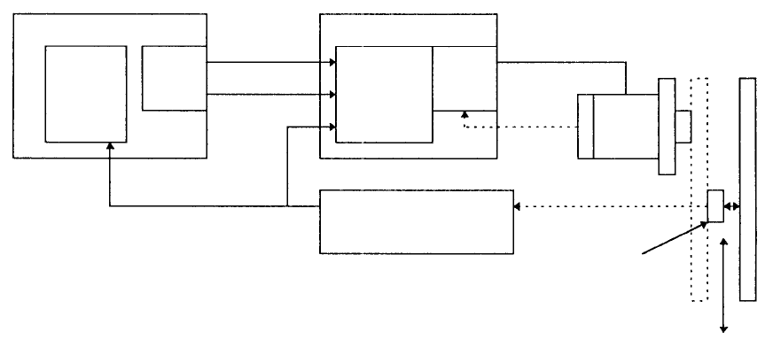
6. DESCRIPTION OF SERVO MOTOR OPERATION
(1) Control system of XY axes
For KE series, a fully closed loop system is sued to control the θ axis of the
IC head, and also the XY axes. The following explains the theory of
operation.
AC servo control board
A
C servo drive
r
q + command
pulse
Power supply for the U, U, W phase drivers
Magnescale
Control
circuit
Memorizes
the current
position of
the
counter.
UP/DOWN
deviation
counter
- command pulse
Motor
w
Speed
detection
e
Magnet
detection
Rotary encoder
t Positioning pulse
Magnescale detector
r Position detection
Sensor head
XY axes
A
xis movement
direction
Figure 6.1 Fully closed loop system
Figure 6.1 shows the fully closed loop system of the XY axes. The example
below explains the operation where XY axes are moved by +100 mm from the
origin.
(1) The SUB CPU1 board of the control unit sets the data such as moving
distance, acceleration/deceleration, and maximum speed of the XY
axes to the AC servo control board, and issues a start command.
(2) At this step, both the counter of the AC servo board and the deviation
counter of the AC servo driver read zero. The profile is created on the
AC servo motor board using the data, and ① + command pulse
according to the acceleration is output to the servo driver.
(3) The number of the command pulses is read by the deviation counter of
the AC servo driver, and the power is supplied to the motor by the
control circuit to start the motor.
(4) The number of pulses from the rotary encoder is counted, the rotating
speed of the motor is detected (② speed detection), and the AC servo
driver controls (speed control) the motor so that it rotates at a constant
speed.
- 125 -