KE-750_MAINTE.pdf - 第109页
3.12 BOC Mark Recognition Operation timing The figure below shows the operation timing of X-Y axes of t he main unit and of the recognition unit for BOC mark recognition. To next action X-Y axes Recognition unit Camera c…
3.11 Part Recognition Process
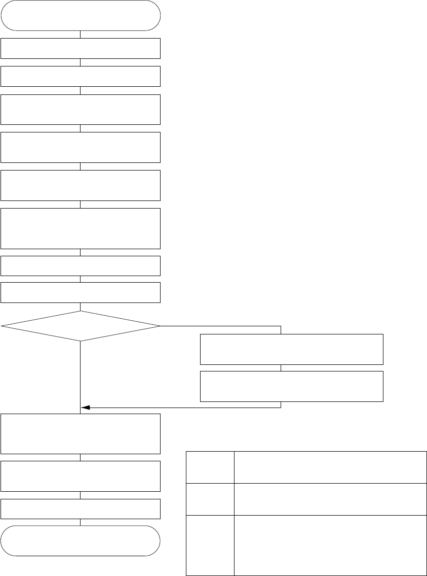
Part recognition using the VCS is performed as shown below:
START
Recognition result, received?
Sends the switch command to the
VCS camera for recognition
Moves the X-Y, Z, and θ axes to the
part recognition unit.
Completes component pick.
Turns on the VCS light.
Sends the part recognition command
to the part recognition unit.
Completes the direct interruption from
the part recognition unit, and waiting
communication reception.
Turns off the VCS light.
Other operations
Obtains the mount coordinate with
which part recognition correction has
been completed.
Moves the X-Y, and θ axes to the
mount coordinate.
Performs mounting.
Moves the X-Y, and θ axes to the coordinate
before part recognition correction.
Waits the result of recognition from the
recognition unit.
End
NO
YES
*1
*2
*1: The coordinates of the axes when part recognition are
as follows:
*2: No action is expected in many cases where mounting is
performed in sequence with the general head which
performs pick and mount with the IC dedicated.
X-Y axes
Z axis
θ axis
The rotating center of the IC head is placed at
the recognition center for the VCS camera.
At the bottom end of the nozzle, and (10 mm
+ part height) from the board surface.
The most nearest direction of the part when
mounted from 0, 90, 180, or 270 degree with
respect to the direction where the direction of
the picked part matches the Y axis direction
of the VCS camera's image.
- 105 -
3.12 BOC Mark Recognition
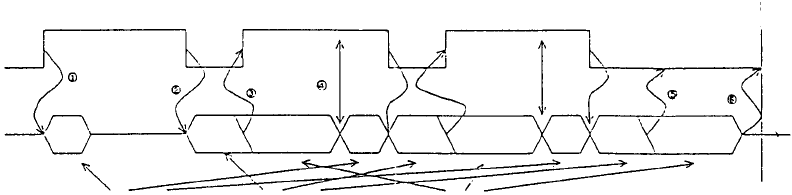
Operation timing
The figure below shows the operation timing of X-Y axes of the main unit and of
the recognition unit for BOC mark recognition.
To next action
X-Y axes
Recognition
unit
Camera change Image recognition Mark recognition
① When BOC recognition operation is started, the X-Y axes are started to
move to the BOC mark recognition position, and, at the same time, the
camera switch command to the BOC camera is sent to the recognition unit.
At this time, the BOC light turns on.
② When movement to the BOC mark recognition position is complete, the
BOC mark recognition command of the recognition unit is sent.
③ When the image recognition completion signal from the recognition unit is
received, the X-Y axes is started to move to the recognition position of the
next mark. After that, the mark recognition process is continued with the
recognition unit.
④ When the result of recognition from the recognition unit is received, the
camera switch command is sent again.
⑤ Steps ② to ④ are repeated until the last BOC mark. When the image of
the last BOC mark is obtained, the BOC light is turned off.
⑥ Waits the result of the image recognition of the last BOC mark from the
recognition unit, and performs the next action.
Recognition sequence
The sequence of BOC mark recognition is different between the BOC mark
recognition per board and the BOC mark recognition per circuit, and they are
performed as follows:
- For the BOC recognition per board
BOC mark recognition is performed from BOC mark position No.1, to No.2, to
No.3 which are shown as the board data.
- 106 -
- For the BOC recognition per circuit
From circuit No.1, in the same manner as for the BOC recognition per board,
BOC mark recognition is performed per circuit. When recognition of all BOC
marks on the circuit is complete, BOC recognition process of the next circuit is
performed in ascending order of the circuit numbers.
The circuit numbers for non-matrix split boards, the order of the number is the
one for the circuit location input from the board data input.
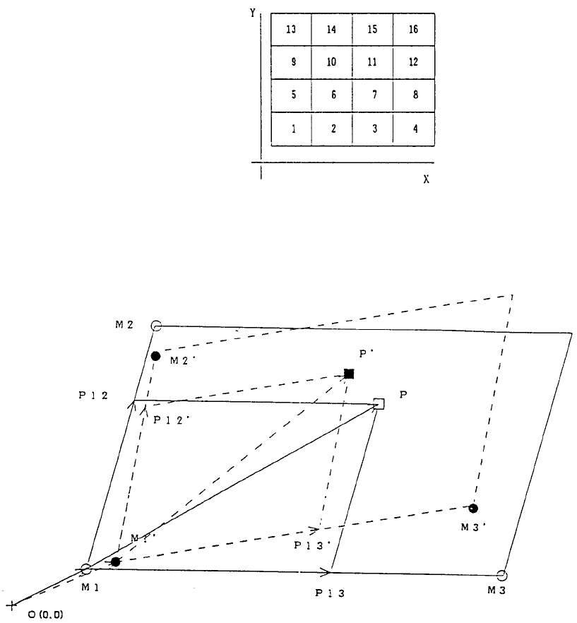
The circuit numbers for matrix split boards, it is to be counted in an increasing
order of the X axis at the side of the circuit close to the machine origin of the X
axis. This is repeated in increasing order of the Y axis from the machine origin
side of the Y axis. For 4 by 4 matrix split boards, the circuit numbers are as
shown below.
Fiducial mark correction algorithm
In case of 3-point BOC mark
When points M1, M2, and M3 shown as (○) in the figure above are the BOC
mark coordinates in the board data, and when the actual coordinates obtained
by the recognition of each point are M1', M2', and M3' shown as (●), obtain
point P' (■) which is the actual mount coordinate with respect to point P (□)
- 107 -