Vermes MDS 358X user Manual.pdf - 第125页
Communication Interfaces 114 VTK - TR -BA- 072e - 1 - User Manua l MDS 358X S eries 8.2.2 PLC - Signals The follow ing graph s show you t he dif ferent P LC - signa ls Trigg er, DosOK and Si n gleDosOK an d thei r behavi…
Communication Interfaces
VTK-TR-BA-072e-1 - User Manual MDS 358X Series
113
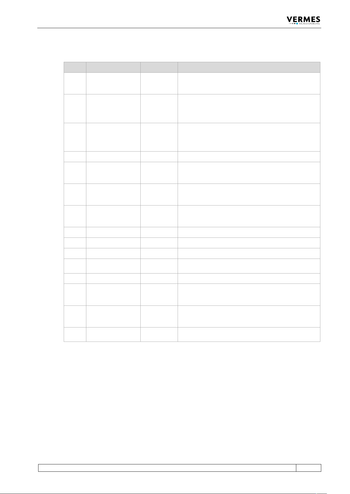
8.2.1 Pin Functions
PIN Characteristics Level Function
1
Output
0 / +24 V,
Ra=2.2 kΩ
(valid for 0 V)
SingleDosOK
2
Input
0 / +24 V
Ri=1.3 kΩ
Trigger Voltage Input
0 ... +5 V “Valve closed“
+12 V ... +30 V “Valve opened“
Positive edge triggering
3
Input
0/ +5 V
Ri=400 Ω
Trigger Voltage Input
0 ... +0.8 V “Valve closed“
+3 V ... +5 V “Valve opened“
Positive edge triggering
4
Ground
___________
Ground
5
Output
0 / +24 V,
Ra=2.2 kΩ
(valid for 0 V)
Set point Heating OK
6
Output
0 / +24 V,
Ra=2.2 kΩ
(valid for 0 V)
Nozzle unit “adjusted” OK
(means green adjust LED)
7
Output
0 / +24 V,
Ra=2.2 kΩ
(valid for 0 V)
Mains voltage OK
8
Reserved
___________
___________
9
Output
24 V/50 mA
Power supply to external trigger
10
Ground
___________
Ground
11
Input
0 / 20 mA,
Ri=500 Ω
Trigger Current Input
12
Reserved
___________
___________
13
Output
0 / +24 V,
Ra=2.2 kΩ
(valid for 0 V)
For adjust: adjust failed. Adjust screw screwed in too
deep or not enough.
Outside adjust: general error (24 V = error)
14
Output
0 / +24 V,
Ra=2.2 kΩ
(valid for 0 V)
DosOK – Ready for dispensing (in the case of a pulse
package, at the end of the entire burst)
15
Input
___________
Trigger Abort; connection to ground, to interrupt
dispensing cycle; trigger blocked while active
Communication Interfaces
114
VTK-TR-BA-072e-1 - User Manual MDS 358X Series
8.2.2 PLC-Signals
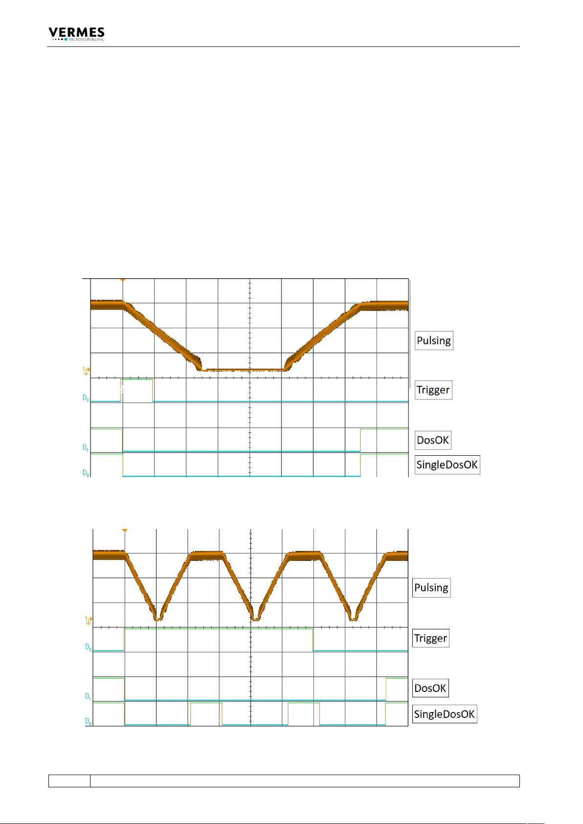
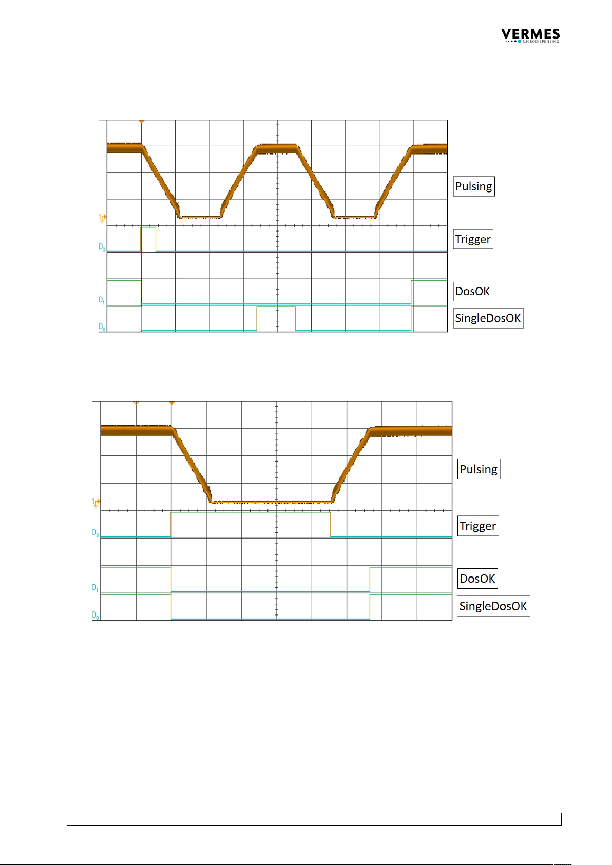
The following graphs show you the different PLC-signals Trigger, DosOK and SingleDosOK and
their behavior in various dispensing modes. The last paragraph then shows the effect of
scenarios. It also shows the differences for the variants of DosOK (Delay ON and Delay OFF) and
SingleDosOK (pulse and setup).
DosOK
The signal DosOK shows the length of a dispensing burst. During the pulsing burst, the signal is
“low”.
SingleDosOK
The signal SingleDosOK shows, that a single shot is being dispensed. When the signal changes to
“low”, a single shot is started. When the signal jumps back to “high”, it shows that the Open Time
has ended and the valve is closed.
8.2.2.1 Single-Shot Mode
Fig. 63: Single-Shot Mode
8.2.2.2 Burst Mode (Example with Three Shots)
Fig. 64: Burst Mode (Example with Three Shots)
Communication Interfaces
VTK-TR-BA-072e-1 - User Manual MDS 358X Series
115
8.2.2.3 External Mode
Fig. 65: External Mode
8.2.2.4 Infinite Mode
Fig. 66: Infinite Mode