Vermes MDS 358X user Manual.pdf - 第31页
Control Unit MDC 20 VTK - TR -BA- 072e - 1 - User Manua l MDS 358X S eries 4 Cont rol Unit MD C This chapter c ontain s relevant inf ormation a bout th e control uni t. It describes the m enu struct ure, key pad an d fun…
General Instructions
VTK-TR-BA-072e-1 - User Manual MDS 358X Series
19
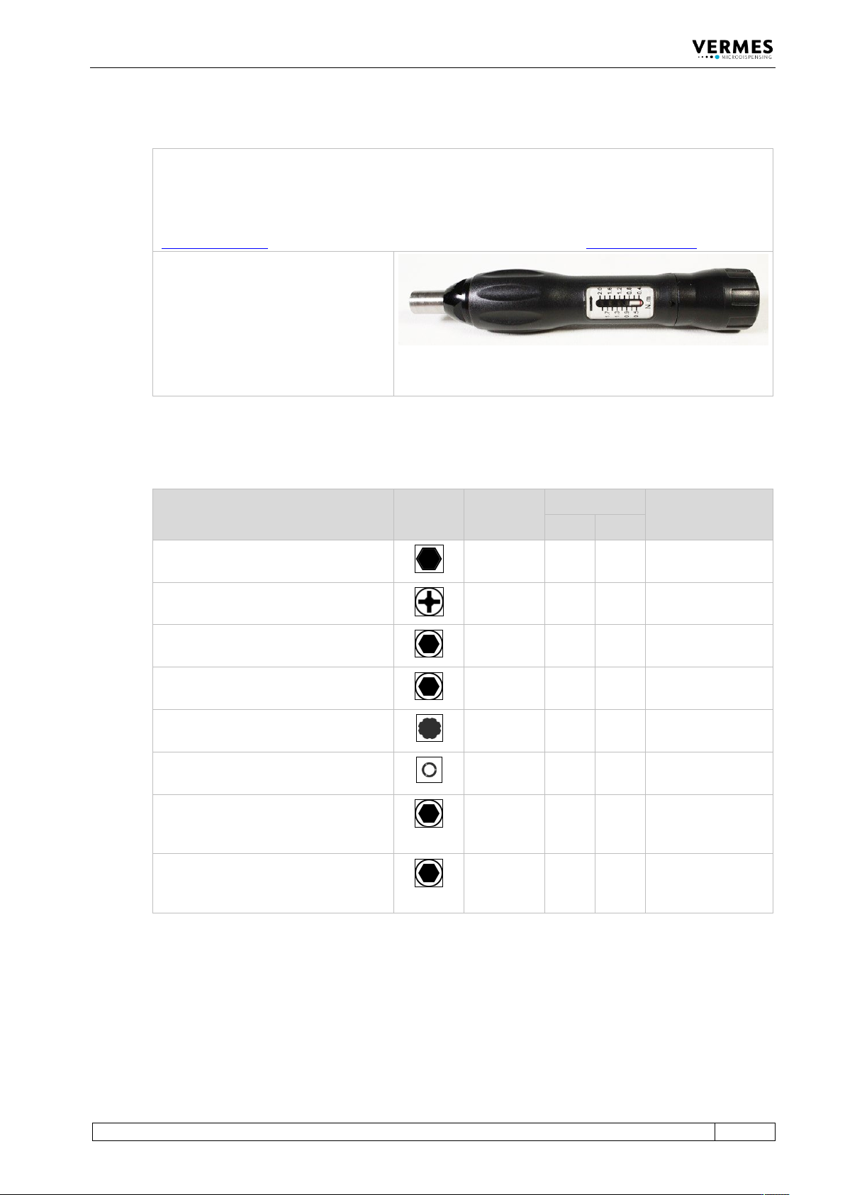
3.3.10 MDT 306 - Torque Wrench Tool VM black
The MDT 306 allows you to screw tight screws with an exactly set tightening torque. The value can be
adjusted continuously at the torque wrench tool.
You can order the necessary bits separately or together with the torque wrench as a set in a tool box
(MDTS 1 - Torque Wrench Tool Set TA, order no. 1013521). Additional information is in the Quick
Reference Guide “Torque Wrench Tool VM MDT 306”. You can download it from the VERMES homepage
(www.vermes.com). The necessary password you can get from our sales (sales@vermes.com
).
Intended Purpose:
1. Tightening screw
2. Tappet Centering Screw BY
3. Cartridge holder
4. Fluid box connector Luer-Lock
5. Nozzle Fixation Nut
6. MDC front panel
7. Valve screws
Tab. 15: MDT 306 - Torque Wrench Tool VM (Order no. 1015062)
3.3.11 Torques (in cN.m)
Element Gearing
Profile
Bit
Order No.
Torque (cN.m) Cross Reference
Min. Max.
Nozzle Fixation Nut
(hexagon screw, size M7)
1014204
150
180
Page 39
Screws for MDC front panel
(cross recess screw, size M3)
1013373
30
40
Page 49
Screws for cartridge holder M 3 x 5
(hexagon socket, size 2)
1013294
40
50
Page 45
Screws for isolation body M 3 x 5
(hexagon socket, size 2)
1013294
40
50
Page 41
Tightening screw
(gearing VM-A)
1014519
120
140
Page 45
Tappet centering screw BY
(gearing VM-B)
1014521
100
140
Page 41
Connector BY
(into mounting body PEEK, hexagon
socket, size 2.5)
1016631
70
80
Page 45
Connector BY
(into mounting body metal, hexagon
socket, size 2.5)
1016631
90
100
Page 45
Tab. 16: Torques (in cN.m)
Control Unit MDC
20
VTK-TR-BA-072e-1 - User Manual MDS 358X Series
4 Control Unit MDC
This chapter contains relevant information about the control unit. It describes the menu
structure, keypad and functions of the control unit.
4.1 Technical Data
Value
Dimensions
128 mm H x 102 mm W x 173 mm D (w/o Kabel)
(see dimensional drawing, Page 165)
3 RU x 20 HP
Weight
ca. 1500 g
Supply Voltage
48 V DC
Current Consumption
Max. 8 A
During start-up, this value can increase by a factor
of 5 (start-up peak).
Ambient Temperature
10 °C - 50 °C
Air Humidity
The relative humidity rH might not surpass 80% at
31 °C or 50% at 50 °C (connect linearly for other
temperatures).
Casing Type
Plug-in case for 19“ rack
Color of Casing
Black, with lighter front panel
Ventilation
Convection
Internal Storage Locations:
10
Display Lines
2 lines with 16 characters each
Display Color
White with background lighting
Keypad
12 softkeys
Color of Keys
Blue, beige
Control Lamps (Front)
1x Heating circuit (red)
1x Maintenance (red)
1x Cooling/Adjust OK (green)
1x Attention/Adjust not OK (red)
Control Lamps (Back)
1x Illuminated power lamp
Plug Contacts (Back)
1x Mains plug (48 V DC)
1x 9 pin Sub-D RS-232C
1x 15 pin Sub-D PLC
1x AUX-socket 24V
1x Sensor socket
1x Actuator socket
1x Socket for heating
1x Socket for cooling

Control Unit MDC
VTK-TR-BA-072e-1 - User Manual MDS 358X Series
21
4.2 Front Side
Fig. 1: Front Side
1 Mounting hole
2 LC display
3 Keypad with 12 soft keys
4 Control lamp for maintenance
“red”
5 Control lamp for cooling/adjust
“green”
6 Control lamp for attention/adjust
“red”
7 Control lamp for status of
heating “red”
LC display:
Data, service intervals and menu options are shown in the two lines of the illuminated LC display
(LCD = “liquid crystal display”). The current menu option appears in the upper line. The lower line
contains the current parameter value for dispensing, according to numerical data to be modified.
Keypad with 12 softkeys:
Menu options to control the system are selected by means of these keys.
Details for changing parameters etc. are explained in a following chapter (see paragraph 4.4,
page 25).
Control lamp for maintenance:
As soon as this lamp lights up, it is recommended to return the valve to the manufacturer (or
licensed subcontractor) for regular periodic maintenance.
Control lamp for cooling/adjust (green):
This green LED has two purposes.
During the adjust, as soon as the LED is ON, the adjust value is OK and can be confirmed by
[enter].