Vermes MDS 358X user Manual.pdf - 第138页
Cleaning VTK - TR -BA- 072e - 1 - User Manua l MDS 358X S eries 127 Optional posit ions The ba yonet f luid box has three dif ferent locki ng positi ons (1: - 90°, 2: 0°, 3: + 90°) in which the va lve can b e operat ed. …
Cleaning
126
VTK-TR-BA-072e-1 - User Manual MDS 358X Series
9.4.3 Demount the Valve
CAUTION
No dispensing medium residues
Before demounting the fluid box from the valve, make sure that no dispensing medium is left
inside the system.
Preliminary steps:
– The dispensing process must be completed. The valve is in closed position.
– Deactivate the compressed air supply and remove the Adapter for Compressed Air.
– Switch OFF the control unit and disconnect it from the mains.
– Remove the actuator cable and sensor cable from the valve.
– Detach the valve with fluid box from dispensing robot.
CAUTION
High temperatures, danger of burns
Be careful if you have used a heater with your application. A nozzle heater can reach
temperatures of up to 180 °C. Do not touch this area before it has cooled, since there is the
danger of severe burns. Use heat resistant gloves.
Disassemble the valve as follows.
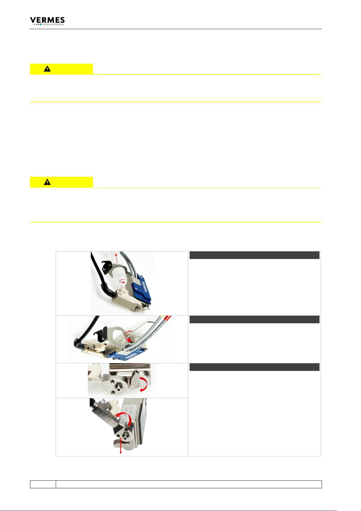
Step 1 (cartridge)
Unscrew and remove the cartridge. First unscrew
the cartridge counter-clockwise, then pull it out.
Step 2 (cartridge holder)
Screw open the two screws for the cartridge
holder (counter-clockwise). Remove the cartridge
holder.
Step 3 (fluid box)
Turn the locking lever by 180° from “Close” to
“Open”.
Turn the fluid box by 45° and pull it off from the
valve.
Cleaning
VTK-TR-BA-072e-1 - User Manual MDS 358X Series
127
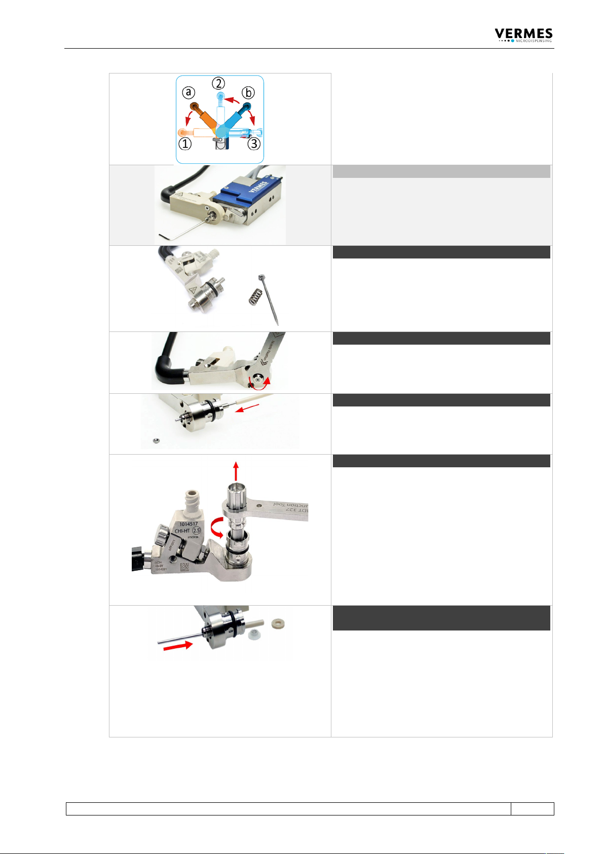
Optional positions
The bayonet fluid box has three different locking
positions (1: -90°, 2: 0°, 3: +90°) in which the valve
can be operated. To open it from locking position
1, turn the fluid box to position a. To open it from
locking position 2 or 3, turn the fluid box to
position b.
Optional (isolation body)
In case you have used an isolation body in your
application, remove it from the fluid box.
Unscrew the two screws for the isolation body
(counter-clockwise). Use the MDT 329 – L-Shape
Hexagon Key.
Step 4 (tappet rod and tappet spring)
Pull the tappet from the fluid box. Pull the tappet
spring from the tappet rod.
Step 5 (nozzle fixation nut)
Remove the nozzle fixation nut by screwing
counter-clockwise. You can use the MDT 327 -
Multi-Function Tool or the MDT 307 - Adjust Tool
TA Hotmelt Handle (with the correct Bit).
Step 6 (nozzle insert)
Use the thin end of MDT 323, to push out the
nozzle insert from behind.
Step 7 (tappet centering screw)
Unscrew the Tappet Centering Screw BY from the
fluid box (counter-clockwise). Use the MDT 303 -
Nozzle Changing Tool.
Make sure the three pins of MDT 303 fit exactly
into the three holes of the Tappet Centering Screw
BY. Turn the MDT 303 counter-clockwise while
pressing it down slightly to the fluid box. Combine
the MDT 303 with MDT 327 for a better leverage.
Step 8 (tappet sealing and tappet centering
piece)
Push out the tappet centering piece and the
tappet sealing from the fluid box. Use the thicker
side of tool MDT 323.
Important note!
There is no tappet centering piece, if you use a
2G tappet rod.
Cleaning
128
VTK-TR-BA-072e-1 - User Manual MDS 358X Series
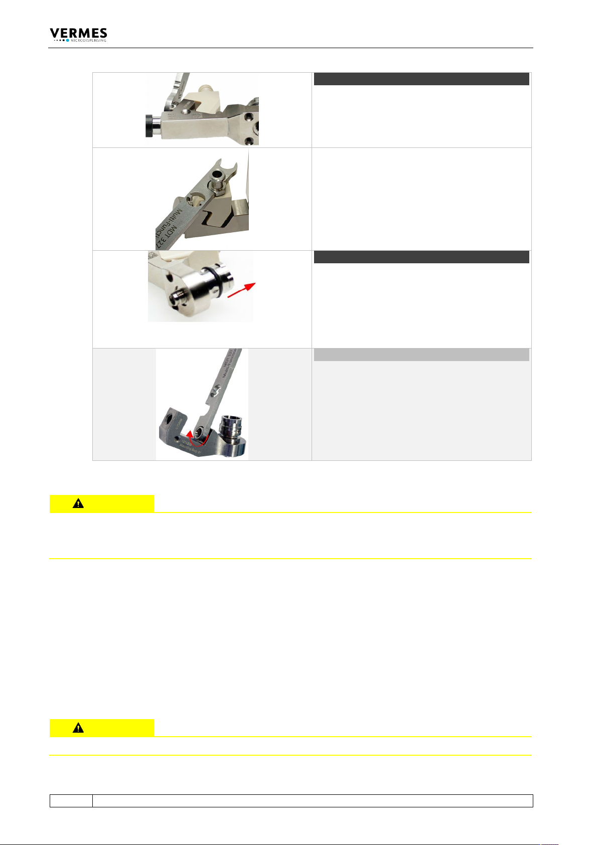
Step 9 (cartridge base)
Unscrew the tightening screw with the help of the
MDT 327 (counter-clockwise). Remove the
tightening screw and the cartridge base from the
fluid box.
Important note!
If you use a Cartridge Base CH, you need to screw
off the Fluid Box Connector Luer Lock first. Use the
open-jawed wrench at the side of the MDT 327
(hexagon screw size M8).
Step 10 (O-ring)
Remove the O-ring from the fluid box body. Pull it
off carefully with a pair of tweezers. Be careful not
to damage the O-ring.
Caution!
You could omit this step, only if the solvent you
use is compatible with the material of the O-ring.
Unusual (connector BY)
Usually you will not remove the Connector BY and
the fluid box body. In case the connector is
clogged, use MDT 327 to screw off the Connector
BY (counter-clockwise). Then pull out the fluid box
body.
Tab. 29: Disassembling of the valve
CAUTION
Damaged tappet sealing
Only use the tools recommended by VERMES. Do not use a sharp tool to press the tappet sealing
from the fluid box. It could cause damage to the tappet sealing, which might lead to a leakage.
9.4.4 Fine Purification
First, clean the single components in an ultrasonic bath.
– Push a cleaning rod or a fluidic brush through the media carrying channels of all the
components.
– Place a beaker in the ultrasonic bath. Make sure it is large enough.
– Place the nozzle insert, tappet sealing, tappet centering piece, cartridge base, tightening
screw, nozzle fixation nut and the fluid box body in the beaker.
CAUTION
Damage of O-ring/tappet sealing