Vermes MDS 358X user Manual.pdf - 第63页
Initial Operation 52 VTK - TR -BA- 072e - 1 - User Manua l MDS 358X S eries 6.3.3.2 Se nsor Cable This cable wra pped in y ellow is prov ided t o transf er data f rom the s ensor i ntegrat ed in th e valve to th e cont r…
Initial Operation
VTK-TR-BA-072e-1 - User Manual MDS 358X Series
51
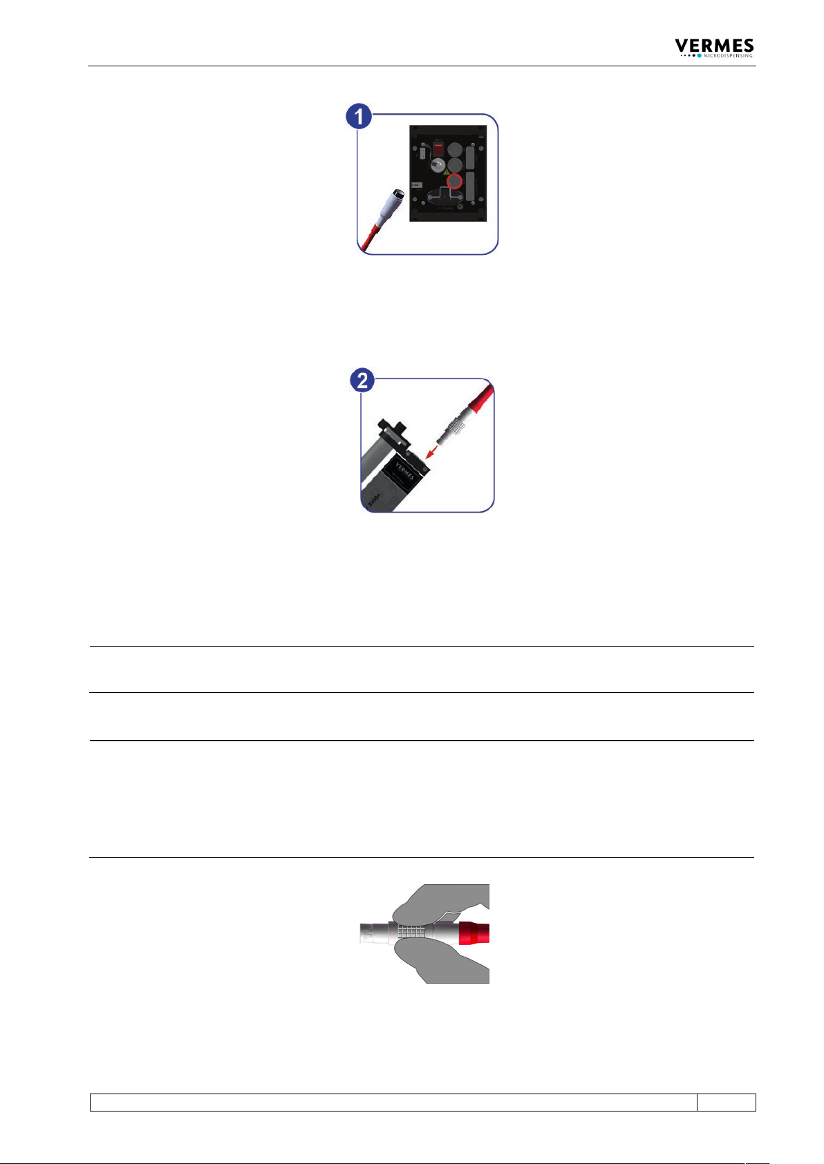
Fig. 22: Connecting the actuator cable – step 1
– Step 1: Plug the cable into the corresponding connector on the rear side of the control unit
and screw it in place.
Fig. 23: Connecting the actuator cable – step 2
– Step 2: The other end, equipped with a four-pin LEMO connector (corrugated sleeve), has to
be connected to the red marked, looped cable attached to the valve.
INFORMATION
Connecting cables
Verify during the connecting procedure that the red dots on the plugs point towards each other.
INFORMATION
Release latch for disconnection
To secure the connectors there is a latch, which you have to release before disconnection. You
have to grip the corrugated outhousing. Pull back the outhousing of the male connector to
release the latch (see Fig. 24). Then pull both connectors apart without losing the grip and they
will separate.
Do not pull at the cables!
Fig. 24: Connector actuator cable - grip
Initial Operation
52
VTK-TR-BA-072e-1 - User Manual MDS 358X Series
6.3.3.2 Sensor Cable
This cable wrapped in yellow is provided to transfer data from the sensor integrated in the valve
to the control unit. Connect it as described below.
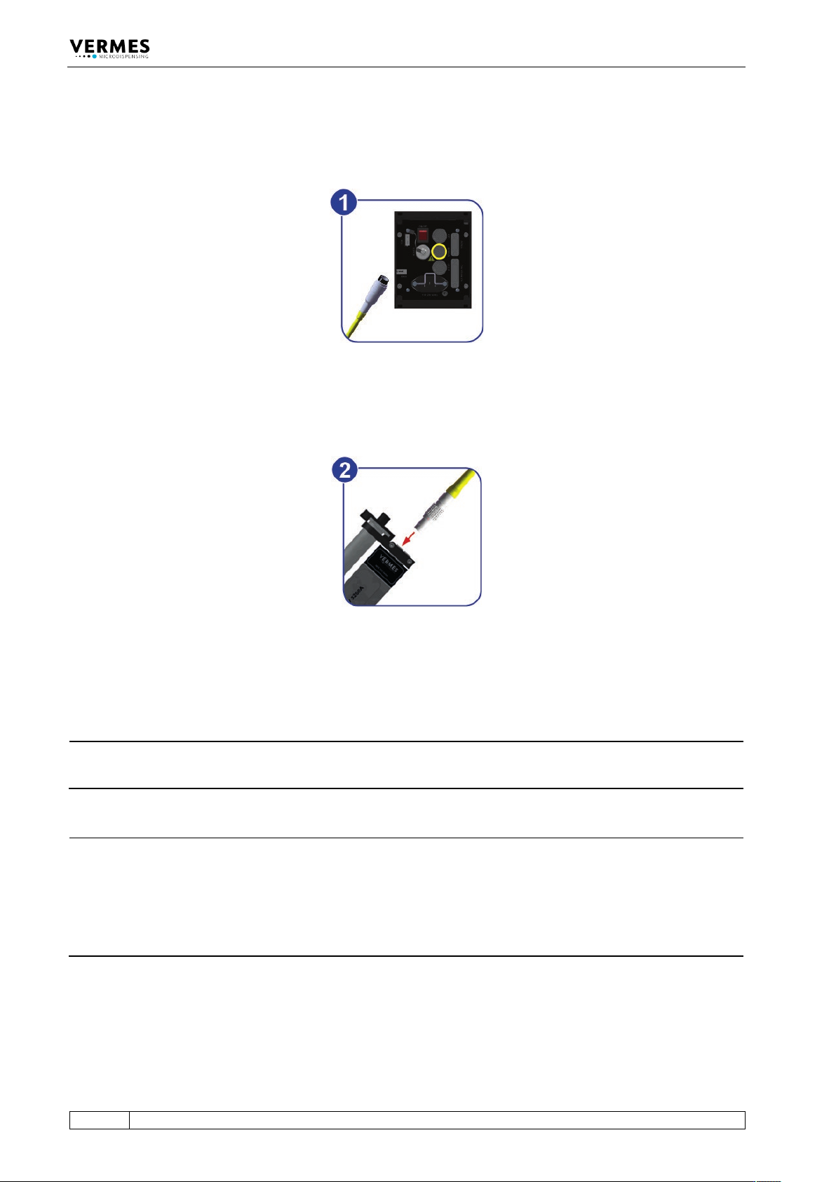
Fig. 25: Connecting the sensor cable – step 1
– Step 1: First, fix the sensor cable to the corresponding socket on the rear side of the control
unit.
Fig. 26: Connecting the sensor cable – step 2
– Step 2: The five-pin connector with a corrugated sleeve has to be connected to the yellow
marked, looped cable attached to the valve.
INFORMATION
Connecting cables
Verify during the connecting procedure that the red dots on the plugs point towards each other.
INFORMATION
Release latch for disconnection
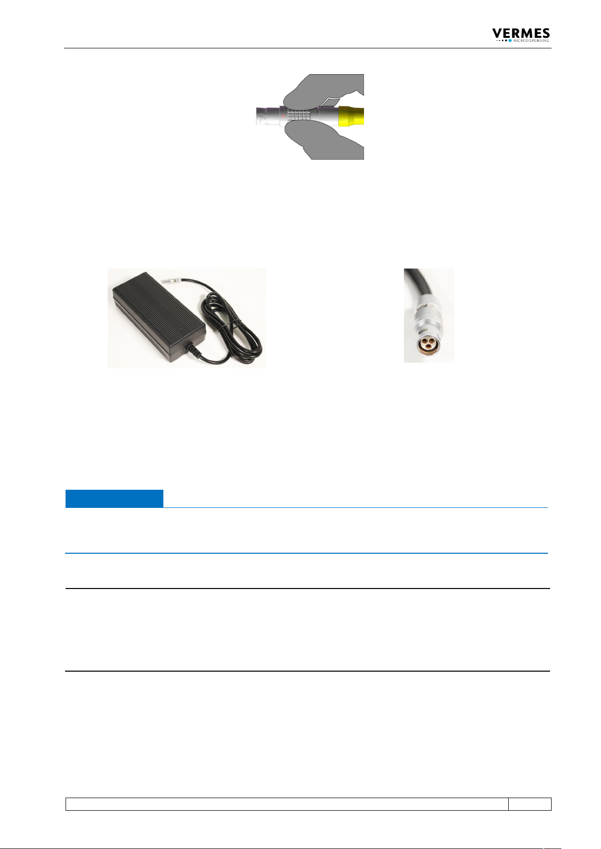
To secure the connectors there is a latch, which you have to release before disconnection. You
have to grip the corrugated outhousing. Pull back the outhousing of the male connector to
release the latch (see Fig. 27, page 53). Then pull both connectors apart without losing the grip
and they will separate.
Do not pull at the cables!
Initial Operation
VTK-TR-BA-072e-1 - User Manual MDS 358X Series
53
Fig. 27: Connector sensor cable - grip
6.3.3.3 Power Supply
Power to the control unit is supplied by the Switching Power Supply 48 V 4 A Push-Pull (order no.
1015251, see picture below).
Fig. 28: Switching Power Supply 48 V 4 A Push-Pull and its connector
– Step 1: Plug the Push-Pull connector into the socket at the bottom of the rear side of the
control unit. You can find the figure of the rear side in paragraph 4.3, page 23.
– Step 2: Connect the Switching Power Supply to the power supply.
– Step 3: Switch on the control unit by pressing the ON/OFF button on the rear side of the
control unit to the position “ON”.
IMPORTANT NOTE
Valve not connected
If a valve is not connected when switch on the MDC, an error message (“101 wrong valve“)
appears on the screen.
INFORMATION
MDC detects the heater and the cooler during start-up
During start-up, the MDC also checks if a heater and/or a flow control valve is connected. The
messages “Heater connected!” (or “Heater is disconnected!”) and “Cooler connected!” (or “Cooler
is disconnected!”) will be displayed. If the setting is selected, that a heater is automatically
activated during start-up, you need to confirm it by pressing the [enter]-key, when a heater is
connected.
6.3.3.4 Connecting a Heater
As an example. the heater MDH-48-BY (order no. 1014231, see Fig. 29, page 54) is shown to
demonstrate the connection of a heater.