Vermes MDS 358X user Manual.pdf - 第129页
Communication Interfaces 118 VTK - TR -BA- 072e - 1 - User Manua l MDS 358X S eries • 5 V or 24 V (PIN2 + PIN4 or PIN3 + PIN4 Inp ut si gnal of MDC via 15 pin Sub - D) • Signal lengt h: 500 μs – 80 ms 3. The sys tem j et…
Communication Interfaces
VTK-TR-BA-072e-1 - User Manual MDS 358X Series
117
Yuki mas nani tipper cat 1
8.2.3 Remote Adjust
8.2.3.1 What is the Remote Adjust?
A remote adjust is similar to a normal adjust (see paragraph 6.5, page 57), but the system is
operated from a master device (e.g. a PC or an XY machine) by means of interfaces (PLC, RS-
232C). The function itself is identical.
8.2.3.2 Advantages
The remote adjust allows for total control of an MDC integrated in a machine, since dispensing
parameters can be monitored by the software of this machine. The control unit can be built in
with permanent key lock. Thus the modification of parameters without authorization can be
prevented in the machine software.
8.2.3.3 Procedure
The remote adjust has to be performed according to the following instructions:
INFORMATION
Displaying remote adjust
• In the beginning of the remote adjust, both adjust LEDs are lit simultaneously.
• The display of the MDC shows “Remote Adjust is running!”
• For transmission of the orders between PC and control unit, the interfaces RS-232C and PLC-
interface are used.
INFORMATION
Preparation before remote adjust
• Screw the nozzle fixation nut absolutely tight (torque at least 150 cN.m).
• The baud rate of the serial interface needs to be set to 115200.
1. Send the command “ADJUST:START” to the control unit via RS-232C. The system returns the
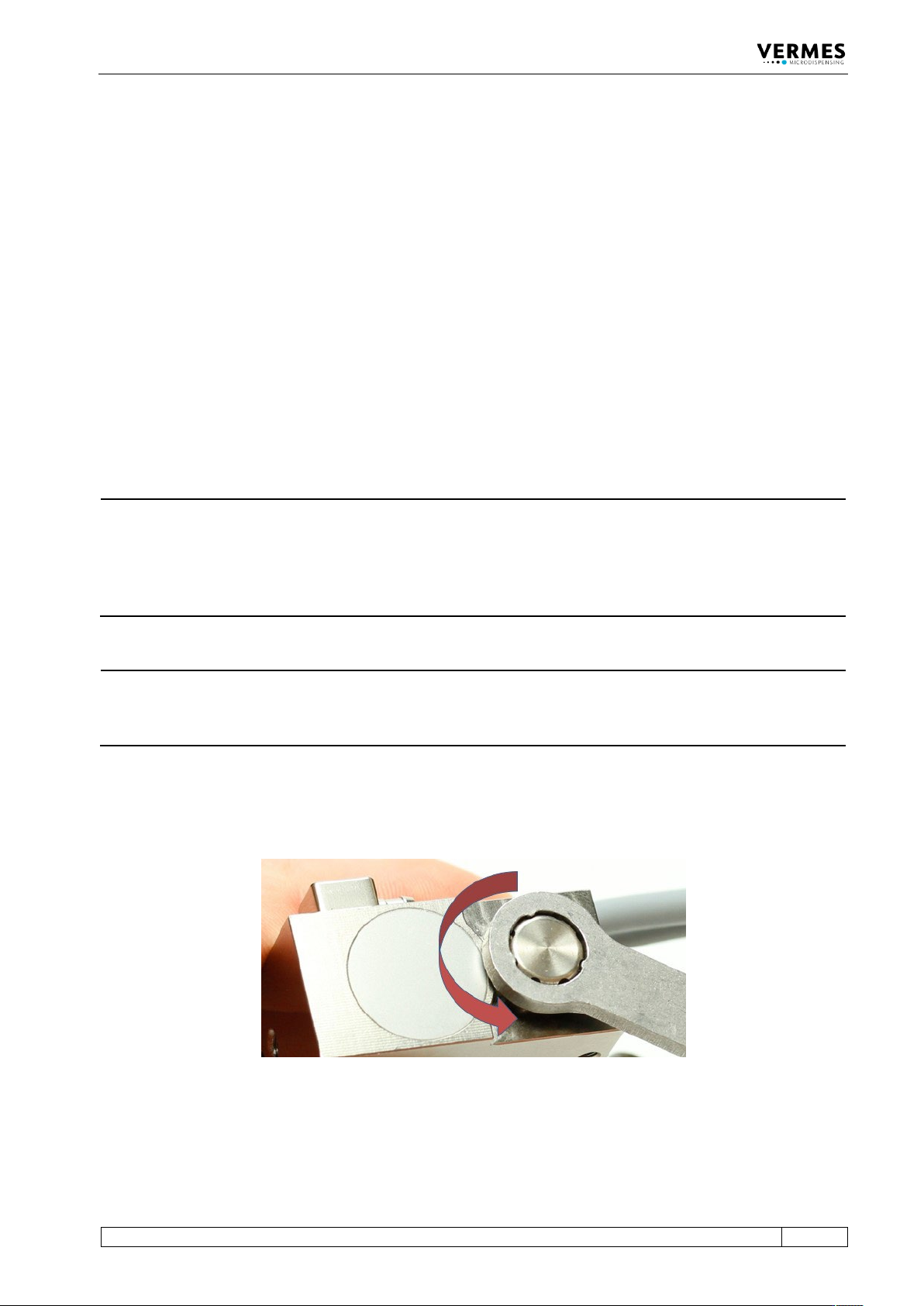
message “Adjust Screw OUT Press Enter”. Screw open the adjust screw completely (counter-
clockwise, see Fig. 69, torque for screwing it open is approx. 50 – 60 cN.m).
Fig. 69: Screw open adjust screw
2. In order to confirm step 1, send a short trigger signal (500 μs – 80 ms) to the control unit via
PLC interface.
Short trigger signal:
Communication Interfaces
118
VTK-TR-BA-072e-1 - User Manual MDS 358X Series
• 5 V or 24 V (PIN2 + PIN4 or PIN3 + PIN4 Input signal of MDC via 15 pin Sub-D)
• Signal length: 500 μs – 80 ms
3. The system jets 500 shots to clear the valve for the remote adjust. The message “500 Shots
Please Wait” is shown. Then the message “Please wait…” appears.
4. The message “Adjust Screw IN until GREEN LED ON” appears first. Then the message
alternates with “SLOW-SCREW IN until green LED ON”. The system then returns the current
status of the adjust LEDs, continuously repeating the transmission to the PC in intervals of 500
ms (via RS-232C). An additional command to update the status of the adjust LEDs on the
screen is not required.
5. Turn the adjust screw inwards (clockwise), until the message displayed on the PC is changed
to “Adjust LED GREEN press enter”. The green adjust LED on the MDC is lit.
6. In order to confirm the remote adjust, send a short trigger signal (500 μs – 80 ms) to the
control unit via PLC interface (see Step 2). This will only be accepted, if the message “Adjust
LED GREEN press enter” is shown. After the confirmation, the system then returns the
following response via RS-232C: “Adjust Success”.
The remote adjust has been completed successfully.
In case you had turned the adjust screw too far, the message “Adjust LED RED Adjust Screw OUT”
appears. Turn the adjust screw outwards (counter-clockwise), until the message “Adjust LED
GREEN press enter” appears. Confirm the remote adjust as described (see Step 6).
The remote adjust can be aborted anytime by sending a long trigger signal (110 ms – 200 ms) to
the control unit via PLC- interface. The system returns the message “Adjust failed” to the PC.
Long trigger signal:
• 5 V or 24 V (PIN2 + PIN4 or PIN3 + PIN4 Input signal of MDC via 15 pin Sub-D)
• Signal length: 110 ms – 200 ms
INFORMATION
Remote adjust deactivates heater and cooling
In case heater or cooling are still ON, they will be automatically deactivated by a remote adjust.
After you have performed the remote adjust, the cooling will be automatically switched back to
the ON/OFF status before the remote adjust. But the heater needs to be turned ON again
manually, if you need it for your application.
Communication Interfaces
VTK-TR-BA-072e-1 - User Manual MDS 358X Series
119
8.3 AUX socket
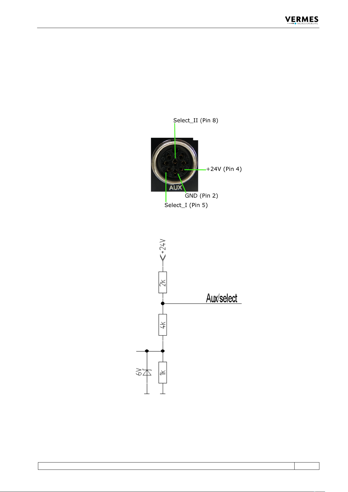
The AUX socket can be used for the supply of an external device (e.g. an optocoupler) or to
control certain setups (see paragraph 7.8, page 68) or scenarios (see paragraph 7.9, page 70). The
pin assignments are shown below (see Fig. 70). In case the select pins are activated, the
maximum current is 12 mA. The other pins are used internally and cannot be used otherwise. The
socket is a Lumberg SV81 8P.
Fig. 70: AUX socket
Fig. 71: Circuit diagram