Vermes MDS 358X user Manual.pdf - 第52页
Micro disp en sing Va lve VTK - TR -BA- 072e - 1 - User Manua l MDS 358X S eries 41 5.2 Explo sion V iew V alve The exp losion view of a n MDV 3 58 0. Usually th e cable c onnections poi nt upwa rds, but on request, they…

Microdispensing Valve
40
VTK-TR-BA-072e-1 - User Manual MDS 358X Series
The valve body (1) accommodates the electronics module, the actuator system, the adjust screw
and the tappet (not visible in the picture). The electronics module holds the electronics to receive
the actuator and sensor signals. Here are the connectors for sensor cable and actuator cable
integrated in the surface of the case; they have to be linked to the control unit. The electronics
module is connected to the actuator system, representing the core of the microdispensing valve.
The actuator system houses the sensor, the piezoelectric element and the mechanics to drive the
tappet. Actuator case and mechanics are sealed for protection against dust and contamination.
The adjust screw (8) is at the top end of the valve body.
At the bottom of the valve is the inlet where the tappet (2) runs. The tappet can be exchanged.
Powered by the actuator the tappet moves with high speed back and forth. It hits the dispensing
medium and presses it through the opening of the nozzle insert. Tappets can be made of
ceramics, of carbide metal or of poly diamond. They can have different forms or sizes. A tappet
should be checked and cleaned regularly or exchanged if necessary (see paragraph 10.2.1
"Maintenance of the Tappet", page 138).
The connection between valve body and fluid box is made up of the tappet sealing (3). There are
different types of tappet sealings, e.g. the Tappet Sealings PE and Tappet Sealings PTFE, which
have to be used together with a tappet centering piece.
A small but important module is the nozzle insert (4), which has to be considered as a wearing
part. Thanks to the bayonet fluid box, it can easily be cleaned and exchanged in case of need.
VERMES Microdispensing offers a large selection of different nozzle inserts to allow for optimum
dispensing results, according to the current application. They can differ in form and material.
The nozzle fixation nut (5) contains the nozzle insert (NI).
The fluid box (6) is integrated into the heater MDH-48-BY. It is thermally isolated from the
actuator system. Its purpose is to transport the liquid from the cartridge or the tank to the nozzle
fixation nut. In order to simplify independent cleaning, this module can easily be disengaged
from the valve, just by one click, thanks to the bayonet system. Information how to assemble a
fluid box you can find in paragraph 6.2, page 45. In case you need no heating for your
application, you can use the Mounting Body BY (order no. 1014369) instead of the heater MDH-
48-BY.
The media supply (7) supplies the dispensing medium and is connected with the fluid box.
VERMES Microdispensing GmbH has many different configurations available (see Page 158). For
smaller amounts to be dispensed you can use a cartridge. They come in different sizes and types.
For larger amounts, you can use a tube connector to connect a pressure tank with the fluid box.
Microdispensing Valve
VTK-TR-BA-072e-1 - User Manual MDS 358X Series
41
5.2 Explosion View Valve
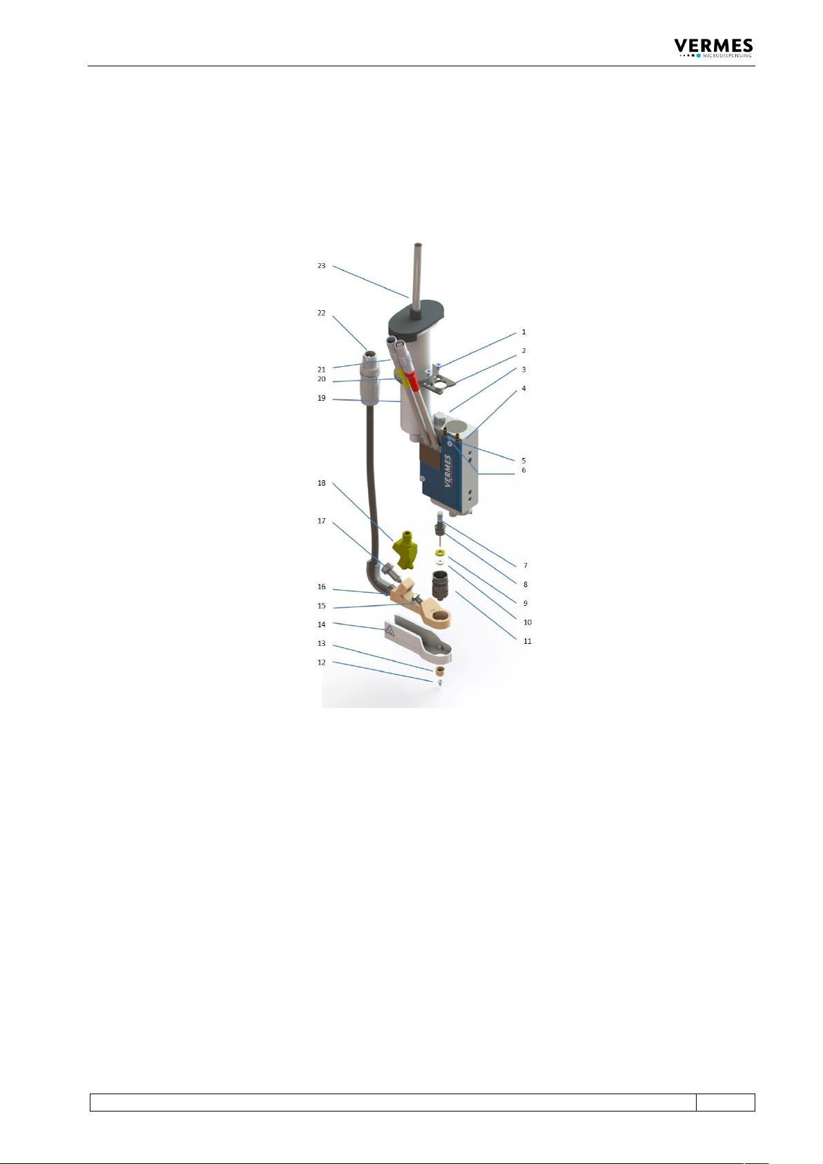
The explosion view of an MDV 3580. Usually the cable connections point upwards, but on
request, they can be oriented differently, so that the cables point to the side. You can change the
orientation of the compressed air connections according to your needs. To do so, you will need a
hexagon key, size 1.5.
Fig. 19: Explosion view valve
1 Set of screws for cartridge holder
2 Cartridge holder
3 Adjust screw
4 Microdispensing valve
5 Connections for compressed air
for valve cooling – in (use
optional)
6 Connections for compressed air
for valve cooling – out (use
optional)
7 Tappet rod with tappet spring
8 Tappet centering screw
9 Tappet centering piece
10 Tappet sealing PE
11 Fluid box body with O-ring BY
12 Nozzle insert
13 Nozzle fixation nut
14 Isolation body (optional)
15 Connector BY
16 Heater MDH-48-BY
17 Tightening screw
18 Cartridge base CHI
19 Cartridge
20 Cable connection – Actuator
(red)
21 Cable connection – Sensor
(yellow)
22 Connection for heater cable
23 Connection for compressed air
Microdispensing Valve
42
VTK-TR-BA-072e-1 - User Manual MDS 358X Series
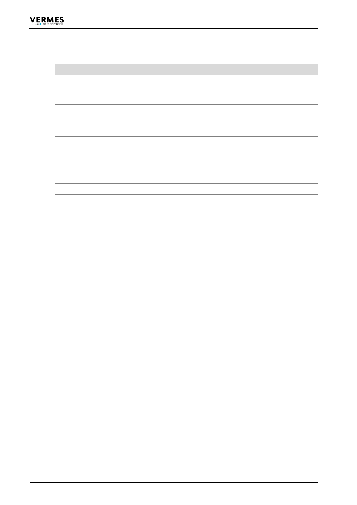
5.3 Technical Data
Parameter Value
Dispensable Quantity
Down to 0.4 nl per cycle (for highly viscous
medium)
Inlet Pressure Range
Depending on the supply unit
(e.g. cartridge or pressure tank)
Dynamic Viscosity of Fluids
Low to high viscosity up to 2000000 mPas
Response Time (PLC-interface)
ca. 130 µs
Dispensing Frequency (max.)
> 3 kHz
Dispensing Frequency (average)
> 1 kHz
Compatibility
all aqueous fluids, organic solvents, weak acids and
bases
Dimensions (basic model)
92.1 mm x 41.5 mm x 36.5 mm
Weight
ca. 250 g (depending on configuration)
Position of Tappet in Absence of Voltage
open
5.4 Valve Types
Compatible with the MDC 3500 are valves of the following series.
• MDV 3580 (low to high viscosity; top adjust with bayonet fastening)
• MDV 3581 (low to high viscosity; top adjust with bayonet fastening)
• MDV 3583 (low to high viscosity; top adjust with bayonet fastening. You will need the
additional manual Quick Reference Guide MDV 3583.)
• MDV 3583-FH (low to high viscosity; top adjust with bayonet fastening and frame heater. You
will need the additional manual Quick Reference Guide MDV 3583.)
Which type is best suited for your application? This depends on different criteria. Air cooled
valves should be your choice, if you dispense with lots of power or if you use a nozzle heater and
constant temperatures are important.