Vermes MDS 358X user Manual.pdf - 第61页
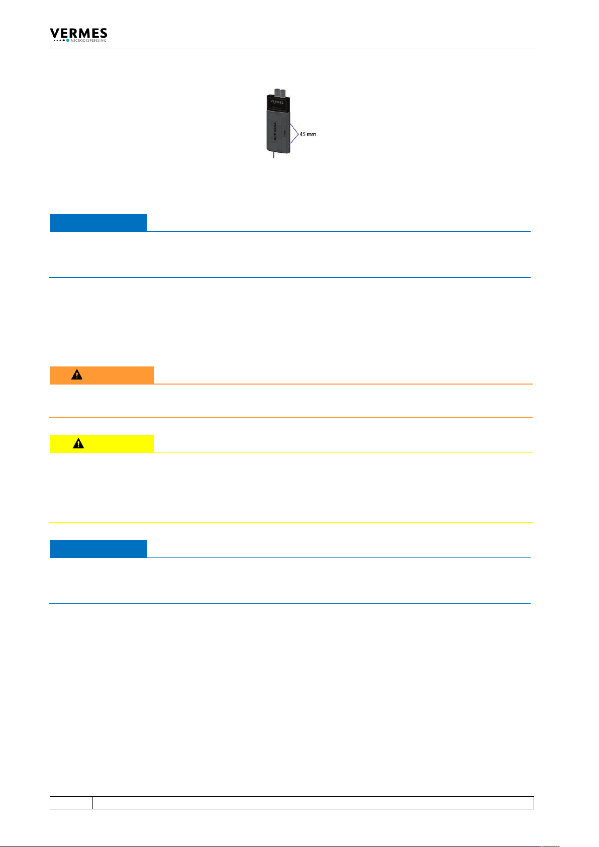
Initial Operation 50 VTK - TR -BA- 072e - 1 - User Manua l MDS 358X S eries Fig. 21 : Distan ce of t he bores 45 mm IMPORTANT NOT E Corrosion In order t o prevent cor rosion , all part s used in conn ecti on with t he va…
Initial Operation
VTK-TR-BA-072e-1 - User Manual MDS 358X Series
49
6.3 Installation of the Microdispensing System
Prior to installation, verify the conditions in the intended location, with respect to the
specification of the system and information detailed in this chapter.
The control unit and the valve have to be installed strictly in conformity with the procedures
described below. The system requires:
• Power supply
• Pneumatic supply
INFORMATION
Read chapter “Safety Notes” first
The entire procedure of installation is reserved to persons reliably informed about the safety
considerations (see chapter 2, page 8).
6.3.1 Installation of the Control Unit
The control unit is designed as a 19” plug-in module, which has to be fixed in the corresponding
rack by means of four pan-head screws at the front side. Leave sufficient space around the unit to
simplify service. Ventilation should be available. Recommended are cases complying with
enclosures according to EN 61010-1 with regard to fire protection.
IMPORTANT NOTE
Potential damage to the control unit
Do not close the four pan-head screws too tight; otherwise the front panel can be damaged (see
torque table Page 19).
To avoid overheating and ensure the required ventilation, a minimum distance between the
control unit and any other object should be maintained (at least 1.5 cm). Heat should neither be
accumulated nor externally be introduced. Do not obstruct natural convection. Ventilation from
the bottom side and air exhaust above is important. Minimum width of ventilation openings is
8 cm x 8 cm.
For high-duty applications (from ca. 300 Hz) or in the case of an air cooled model (AC variants), a
rack with separate ventilation is advisable, since in these situations an airflow of 30 m
3
/h for each
control unit is compulsory.
6.3.2 Installation of the Valve as Part of a Machine
Preferably, mount the valve on an automatic XYZ table or in a similar device (XYZ positioning
system). Stable seat at the fixture of Z-axis is imperative, as the valve should not become loose
during the dispensing process. For this purpose, insert two M4 hex screws to a depth of 4 mm,
through the bores located at the narrow side of the valve. Their distance center to center
amounts to 45 mm. To improve accuracy when positioning the valve on a receptacle,
additionally use the alignment bore and the long hole, located on the narrow side of the valve as
well.
Initial Operation
50
VTK-TR-BA-072e-1 - User Manual MDS 358X Series
Fig. 21: Distance of the bores 45 mm
IMPORTANT NOTE
Corrosion
In order to prevent corrosion, all parts used in connection with the valve (screws, fixing plates
etc.) should consist of stainless steel, nonferrous metals or galvanized steel.
6.3.3 Wiring of the MDS
The valve is connected to the control unit by means of a four-pin actuator plug (red) and five-pin
sensor plug (yellow). The plugs are protected by coding against interchanging by mistake.
WARNING
Switch off before removing plug
Never attempt to attach or remove one of these plugs, when the system is connected to mains.
CAUTION
Plan your cable connections carefully
Make sure to plan your cable run carefully, when considering the wiring, especially if the valve is
included into a more complex system. Your cables cannot hang too loose, since then they might
start to swing and get damaged, because of the vibrations of the valve. On the other hand, you
need enough length in your cables, if the valve is moved in the z-axis.
IMPORTANT NOTE
Switch off for disconnection
Before you disconnect the valve from the control unit or connect it to it, switch OFF the whole
system.
6.3.3.1 Actuator Cable
Power to the piezo element is supplied by the actuator cable, which is wrapped with a red
antikink sleeve. The voltage range is -50 V to 150 V (bipolar operation).
Initial Operation
VTK-TR-BA-072e-1 - User Manual MDS 358X Series
51
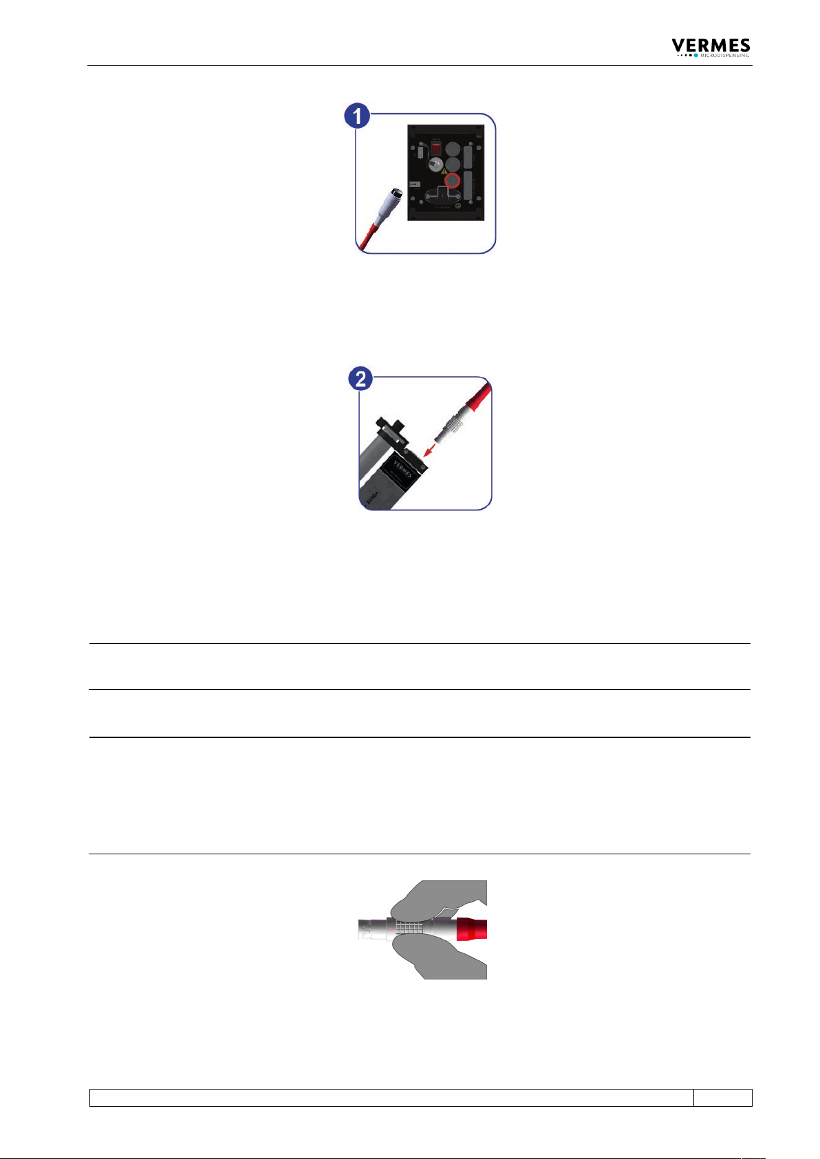
Fig. 22: Connecting the actuator cable – step 1
– Step 1: Plug the cable into the corresponding connector on the rear side of the control unit
and screw it in place.
Fig. 23: Connecting the actuator cable – step 2
– Step 2: The other end, equipped with a four-pin LEMO connector (corrugated sleeve), has to
be connected to the red marked, looped cable attached to the valve.
INFORMATION
Connecting cables
Verify during the connecting procedure that the red dots on the plugs point towards each other.
INFORMATION
Release latch for disconnection
To secure the connectors there is a latch, which you have to release before disconnection. You
have to grip the corrugated outhousing. Pull back the outhousing of the male connector to
release the latch (see Fig. 24). Then pull both connectors apart without losing the grip and they
will separate.
Do not pull at the cables!
Fig. 24: Connector actuator cable - grip