Vermes MDS 358X user Manual.pdf - 第42页
Control Unit MDC VTK - TR -BA- 072e - 1 - User Manua l MDS 358X S eries 31 With “Heater” you can re ach the submenu for t he heater setti n gs ( see paragraph 4.5.3.1 , page 31). 4.5.3.1 Submenu Cooler Th is submen u has…
Control Unit MDC
30
VTK-TR-BA-072e-1 - User Manual MDS 358X Series
4.5.3 Submenu “Cooler/Heater”
A Microdispensing System MDS can be equipped with a heater or a cooling valve. For heating,
you can use a 48 V heater (e.g. Heater MDH-48-BY, order no. 1014231). For cooling, you can use a
flow control valve (e.g. Flow Control Valve FCV-AC 6.0 M12, order no. 1016265).
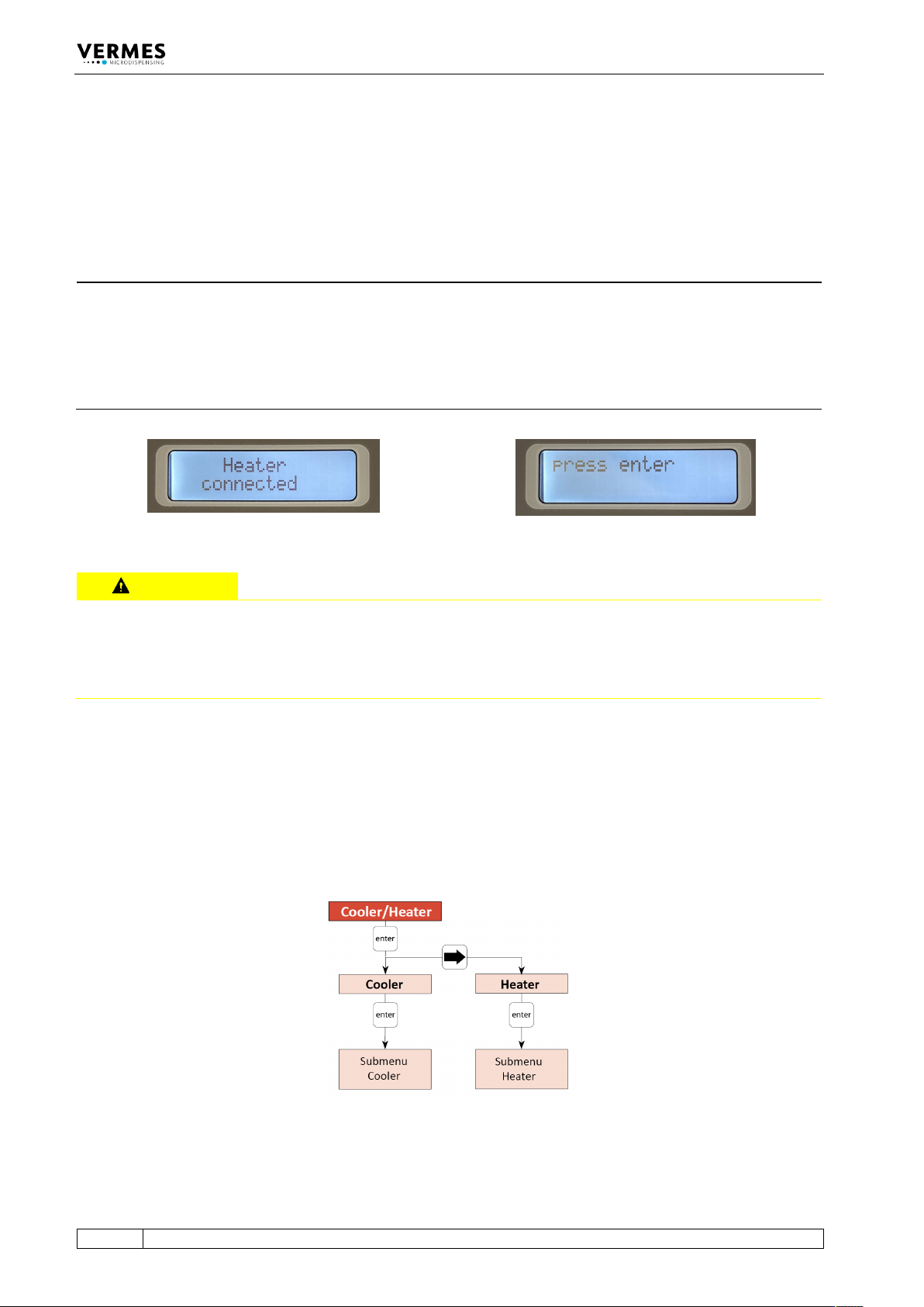
Fig. 8: Message “Heater connected - press enter”
CAUTION
Danger of burns through high temperatures!
The heater can reach temperatures of up to 180 °C.
• Do not touch this area during operation.
• And afterwards only touch it once it has cooled down.
By using a heater, the dynamical viscosity of the fluid to be dispensed can be controlled. For
some liquids, dispensing without heating is impossible. Heating may also be required to ensure a
constant process temperature, or when the dispensing has to take place above room
temperature.
To reach a certain target temperature takes time. This time is influenced by many different
circumstances, e.g. the outer temperatures.
Fig. 9: Submenu “Cooler/Heater”
All relevant functions of the heater and the cooling valve can be set in this submenu. With
“Cooler” you can reach the submenu for the cooling settings (see paragraph 4.5.3.2, page 31).
INFORMATION
MDC detects the heater and the cooler during start-up
During start-up, the MDC also checks if a heater and/or a flow control valve is connected. The
messages “Heater connected” (or “Heater is disconnected!”) and “Cooler connected” (or “Cooler
is disconnected!”) will be displayed. When a heater is connected, the display switches between
the message “Heater connected” and the message “press enter” (see Fig. 8). You need to press
the [enter]-key to confirm it.
Control Unit MDC
VTK-TR-BA-072e-1 - User Manual MDS 358X Series
31
With “Heater” you can reach the submenu for the heater settings (see paragraph 4.5.3.1,
page 31).
4.5.3.1 Submenu Cooler
This submenu has three menu items.
CAUTION
A
void uncontrolled compressed air release
An uncontrolled release of compressed air can cause damages and injuries. Therefore, your
controlling machine needs to have a stopcock with air vent. Additionally, your XY-machine needs
to follow the directives for working with compressed air.
To reach a certain target temperature takes time. This time is influenced by many different
circumstances, e.g. the outer temperatures.
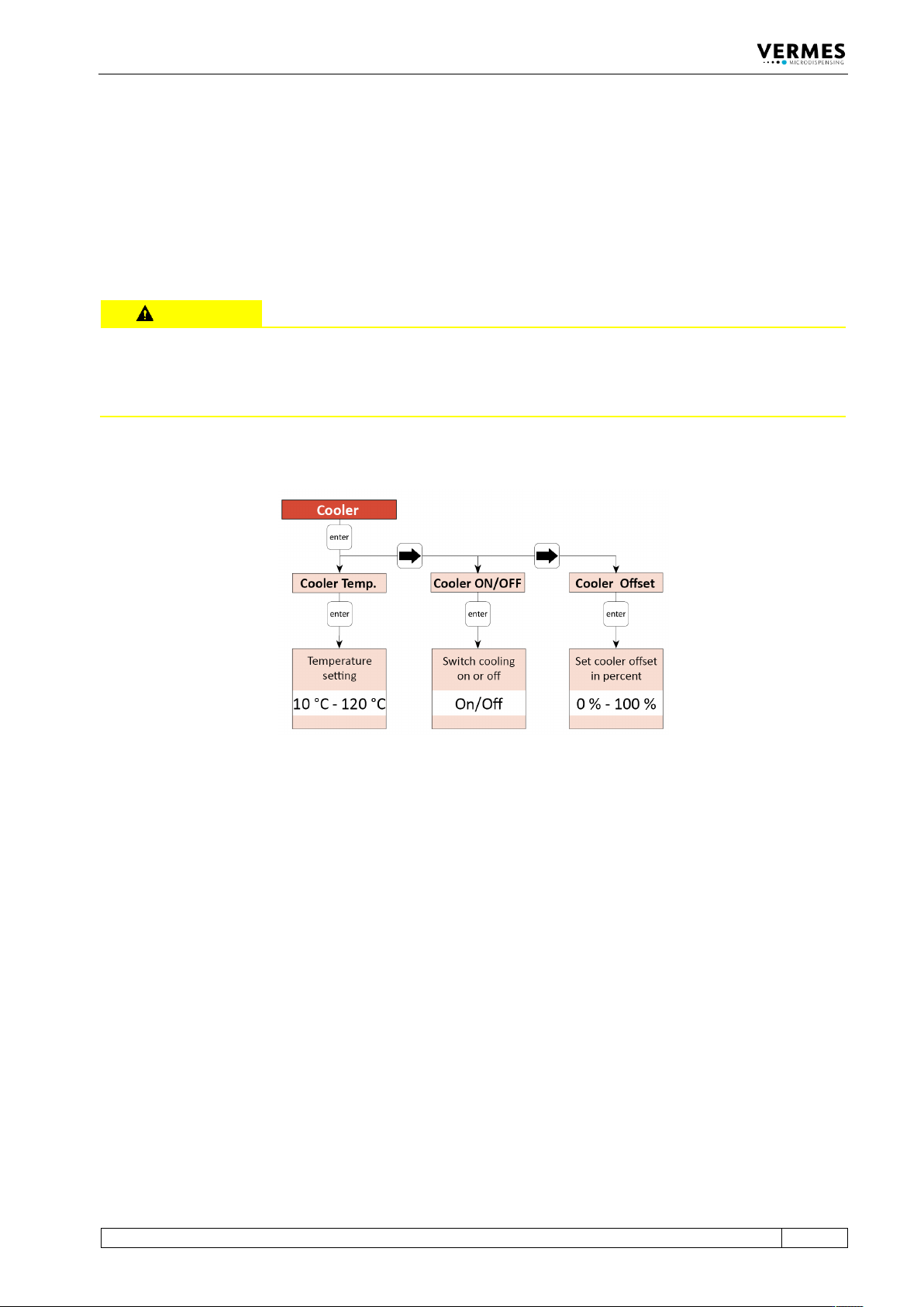
Fig. 10: Submenu “Cooler”
All relevant functions of the cooling system can be set in this submenu. With “Cooler Temp.”, you
can set the temperature with an accuracy of 1 °C. With “Cooler ON/OFF”, you can switch the
cooling valve ON or OFF. “Cooler Offset” allows you to set a cooler offset in percent (see
chapter 7.14.2, page 81). This cooler offset provides an offset value for the flow control valve,
which is independent from the regulation system. The value is given as a percentage value.
In case the cooler is turned ON, if the actuator temperature is more than 10 °C above the target
temperature, the systems starts a more effective cooling. During this fast cooling phase, the
green Cooling LED flashes. Once the actuator temperature falls within 10 °C above the target
temperature, the green Cooling LED no longer flashes, but is ON. For exact dispensing results, the
actuator temperature should stay below 80 °C. If the Error 502 appears (see paragraph 11.2,
page 142), dispensing is only again possible after the actuator temperature falls below 80 °C.
To check information about the cooler (e.g. status, temperatures) via RS-232C interface, send the
command “COOLER:?” (for details see paragraph 8.1.2.2, page 88).
4.5.3.2 Submenu Heater
This submenu has two menu items.
Control Unit MDC
32
VTK-TR-BA-072e-1 - User Manual MDS 358X Series
CAUTION
D
anger of burns through high temperatures!
The nozzle heater can reach very high temperatures.
• Do not touch this area during operation.
• And afterwards only touch it once it has cooled down.
• If possible, wear heat resistant gloves.
To reach a certain target temperature takes time.
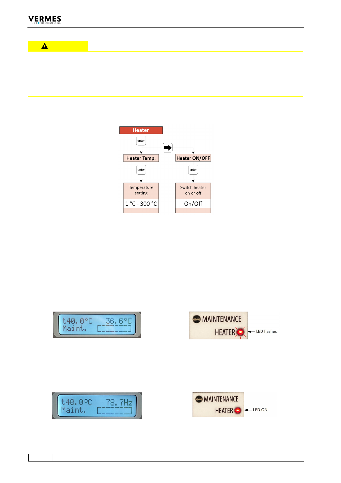
Fig. 11: Submenu “Heater”
All relevant functions of the heater can be set in this submenu. With “Heater Temp.”, you can
select the temperature values with an accuracy of 1 °C. The maximum temperature you can set at
the MDC is 300 °C, but the effective maximum depends on the connected heater (e.g. a
maximum of 180 °C with MDH-48-BY). With “Heater ON/OFF”, you can switch the heater ON and
OFF.
For an example of the display see Fig. 12, when the heater is switched ON, but the target
temperature is not reached yet. The target temperature is shown instead of “Ready” in the upper
left corner of the display. Instead of dispensing frequency, the current temperature is refreshing
in the upper right corner of the display. During this phase, the red Heater LED flashes.
Fig. 12: Before reaching the target temperature
When the target temperature is reached and stable, the dispensing frequency is shown in the
upper right corner of the display (as an example, see Fig. 13). The red Heater LED no longer
flashes, but stays ON.
Fig. 13: The target temperature is reached