Vermes MDS 358X user Manual.pdf - 第148页
Maintenance VTK - TR -BA- 072e - 1 - User Manua l MDS 358X S eries 137 10 M ainte nanc e 10.1 Maintenance Indic ator The in tegrated functi on “Cycle Count” r elates t o the valve as a w hole and i s predetermin ed by th…
Cleaning
136
VTK-TR-BA-072e-1 - User Manual MDS 358X Series
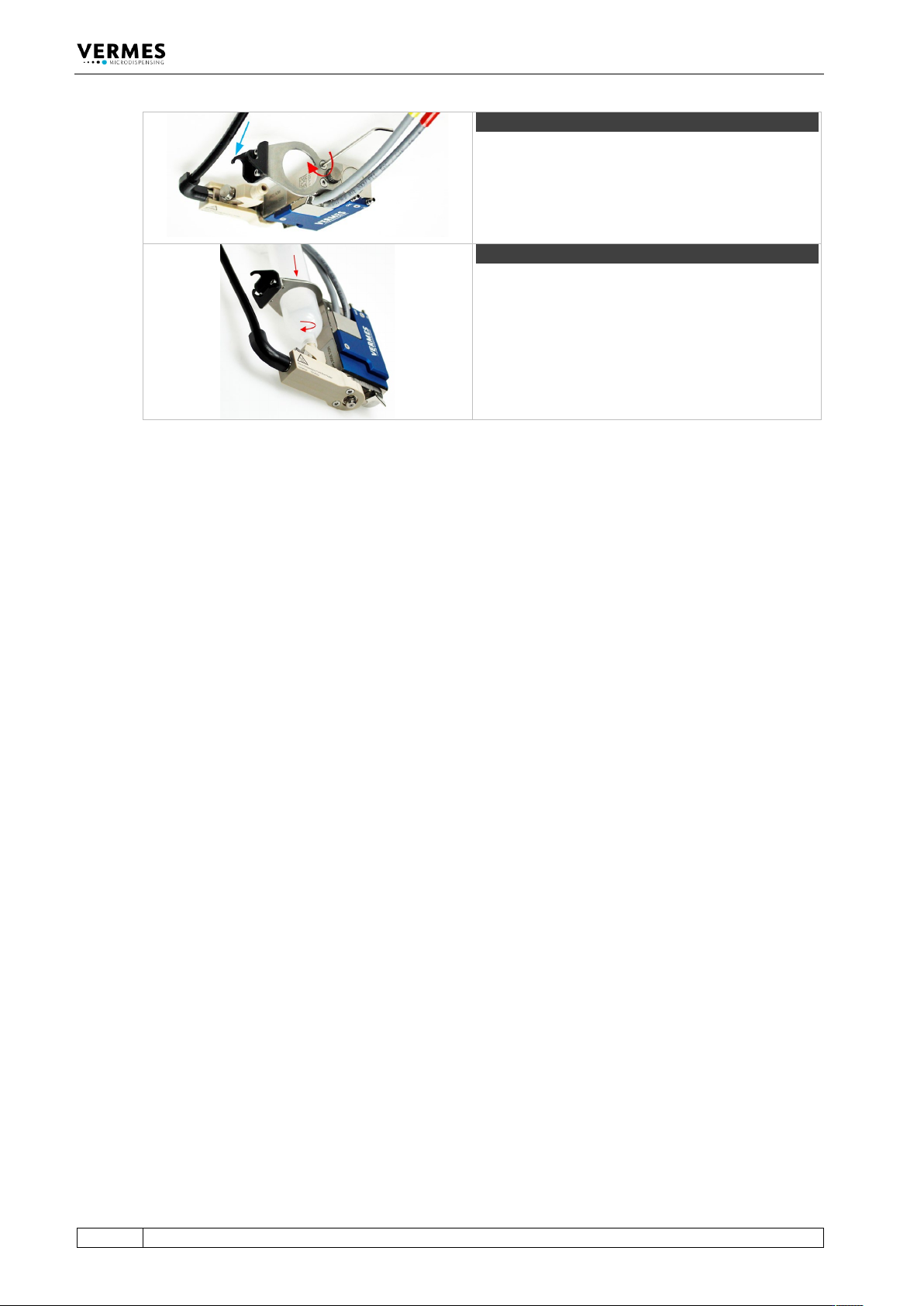
Step 10 (cartridge holder)
Screw the cartridge holder on top of the valve body
(torque between 40 – 50 cN.m). Use the MDT 329 or
a hexagon socket key size 2. Depending on the size
of the cartridge, you have to select the correct
cartridge holder. Hook the heater connection of the
fluid box into the cartridge holder (see blue arrow).
Step 11 (cartridge)
Push the cartridge through the cartridge holder and
screw it clockwise into the thread of the cartridge
base.
Tab. 31: Assembling of the valve
– Finally, connect the actuator and sensor cables as well as the compressed air. You can find
more detailed information in paragraph 6.2, page 45 and paragraph 6.3, page 49.

Maintenance
VTK-TR-BA-072e-1 - User Manual MDS 358X Series
137
10 Maintenance
10.1 Maintenance Indicator
The integrated function “Cycle Count” relates to the valve as a whole and is predetermined by
the manufacturer. As soon as the preset number of cycles is complete (100 %), the red
maintenance LED on the control panel is lit. The manufacturer (or an authorized subcontractor)
has to be informed at once.
In between, you can inspect the current state. Use the function “Maint. Cycle” in the submenu
“Status” (see paragraph 4.5.4, page 34). The result is visualized by eight bars on the screen, each
of them representing 12.5 % of the final value. Be aware that the bar is only updated during a
start-up of the MDC.
INFORMATION
Suppress maintenance messages
Activation of the red maintenance LED can be suppressed by switching “Maint. Message” in the
submenu “Status” to “OFF”. This should only be done, if you know your system very well.
Otherwise, you might cause damages through missed maintenance dates.
Additional cycle numbers can individually be agreed for tappet and nozzle insert. In factory
settings, the value of “Infinite” is assigned to both of the targets. If you wish to check a particular
value, proceed as follows, starting from the first menu level:
• 1x [→]-key = Indicates the interval for exchange of the nozzle insert
• 2x [→]-key = Indicates the interval for exchange of the tappet
To enter a desired final value, you have to use the functions “Set Nozzle” for the nozzle and “Set
Tappet” for the tappet. They are located in the submenu “Status”. Results are also displayed in
the form of 8 bars, each of them representing 12.5 % of the total value. Once 100 % are reached,
the red maintenance LED is lit. The corresponding item (nozzle or tappet) has to be exchanged.
After the exchange, you have to reset the corresponding counter to “0”. Use the functions “Reset
Nozzle” or “Reset Tappet” in submenu “Status” (see paragraph 4.5.4, page 34).
Maintenance
138
VTK-TR-BA-072e-1 - User Manual MDS 358X Series
10.2 Maintenance of Tappet, Tappet Sealing and Nozzle Insert
As the tappet, the tappet sealing and the nozzle insert belong to the wearing parts of the system,
they need to be cleaned and exchanged regularly.
10.2.1 Maintenance of the Tappet
The tappet has to be cleaned and exchanged in regular intervals (at least every 40 million shots)
or in the case of problems (as soon as it starts to move in a sluggish way). Please be aware that
the lifespan of the tappet not only varies by the material and size, but also depends on your
application. Ceramics (CTF, SNTF), tungsten carbide (TTF) and diamond (PDTF) items are
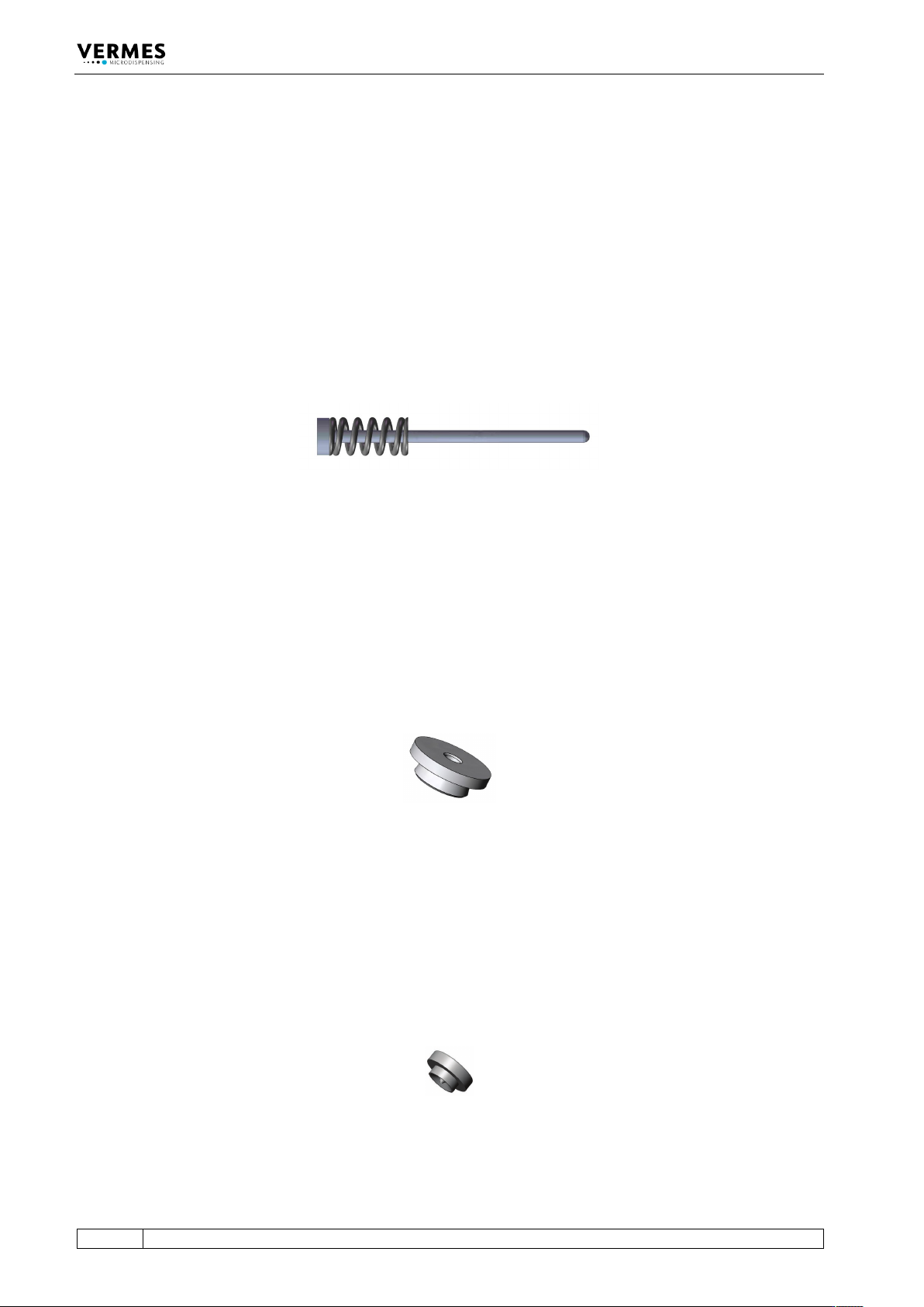
available. The tappet consists of the tappet rod and the tappet spring.
Fig. 72: Example - TTF Tappet (consists of tappet rod and tappet spring)
10.2.2 Maintenance of the Tappet Sealing
For replacement of tappet sealings a particular counter is not provided, as the necessity depends
on current applications, substances to be dispensed etc. Caused by the tappet movement, some
materials tend to penetrate between tappet and tappet sealing, giving rise to abrasion.
Therefore, you have to inspect the tappet sealing from time to time. To continue working with a
damaged tappet sealing inevitably entails unexpected interruptions, loss of material and an
increased need of cleaning. In some cases, even the actuator can be damaged, due to the ingress
of liquid.
Fig. 73: Example - Tappet Sealing PE
10.2.3 Maintenance of the Nozzle Insert
The nozzle insert has to be cleaned and exchanged in regular intervals or in the case of problems.
Please be aware that the lifespan of the nozzle insert depends on your application. After
disassembling the nozzle insert, immediately use a cleaning wire to push through the channel of
the nozzle insert, to avoid hardening of residue medium. Do not use a clogged nozzle insert,
since it would strongly compromise your dispensing results. Exchange the nozzle insert as soon
as it is worn out, since otherwise it can cause a leakage problem.
Fig. 74: Example - Nozzle Insert N11