Vermes MDS 358X user Manual.pdf - 第84页
Operation VTK - TR -BA- 072e - 1 - User Manua l MDS 358X S eries 73 7.10 Factory Setti ngs By reca lling the fact ory set tings (i mplemented by t he manufac turer), y ou retur n to a predefin ed starting position. Thi s…
Operation
72
VTK-TR-BA-072e-1 - User Manual MDS 358X Series
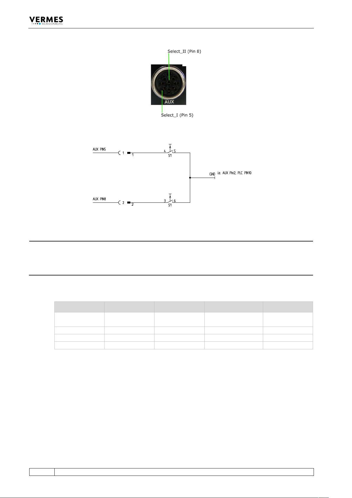
Fig. 53: Select Pins
Fig. 54: Schematic of usage of select pins
INFORMATION
Select pins with other commands
Select pins will be checked for triggering via PLC interface, for the serial commands
VALVE:AOPEN and SVALVE:AOPEN (in the versions without parameters) and when pressing the
key [trig].
You can also simulate the select pin settings for these two commands by using the command
extensions “S0”, “S1”, “S2” or “S3” (see paragraph 8.1.2.2 "Explanations", page 88).
Parameters Select1 Select2 Scenario „OFF“ Scenario „ON“
S0
High
High
Setup 0 (working
configuration)
Scenario 1
S1
Low
High
Setup 1
Scenario 2
S2
High
Low
Setup 2
Scenario 3
S3
Low
Low
Setup 3
Scenario 4
Tab. 23: Select Pin settings
Operation
VTK-TR-BA-072e-1 - User Manual MDS 358X Series
73
7.10 Factory Settings
By recalling the factory settings (implemented by the manufacturer), you return to a predefined
starting position. This is useful to start the input of a new parameter set.
These are the values contained in the factory settings:
RI = 0.50 ms, FA = 0.20 ms, OT = 2.0 ms, NL = 80 %, DL = 10.0 ms and NP = 1.
– Step 1: Press [recall].
– Step 2: [↓] immediately opens this parameter set.
– Step 3: Confirm the selection with [enter].
INFORMATION
Aborting the process
The working configuration (setup 0) is changed to the factory settings. Press [esc] to abort at any
time.
The following table lists the factory settings of the setups.
RI [ms] OT [ms] FA [ms] NL [%] NP DL [ms]
Setup 0
0.50
2.0
0.20
80
1
10.0
Setup 1
1.00
4.0
0.12
80
1
10.0
Setup 2
0.50
2.0
0.20
80
10
10.0
Setup 3
0.40
0.6
0.16
80
1
10.0
Tab. 24: Factory settings of the setups
With Setup ALL (see paragraph 4.5.6 "Submenu “Service-Option”", page 37) Setup 4 – 10 get the
same values as setup 0 (working configuration).
The factory settings for all four scenarios are the same. The PLCStop is “OFF”, the other
parameters are shown in the following table.
Sc.-Segment Setup used ScNP Sc.-Delay
Segment 1
0
as setup NP
10.0 ms
Segment 2
1
as setup NP
10.0 ms
Segment 3
2
as setup NP
10.0 ms
Segment 4
3
as setup NP
10.0 ms
Segment 5
0
as setup NP
10.0 ms
Segment 6
1
as setup NP
10.0 ms
Segment 7
2
as setup NP
10.0 ms
Segment 8
3
as setup NP
10.0 ms
Segment 9
0
as setup NP
10.0 ms
Segment 10
1
as setup NP
10.0 ms
Tab. 25: Factory settings of the scenarios
You can use the menu to reset changed parameters to their factory settings. Go to the submenu
“Service-Option” and press [enter] at “Service Code“. You can enter the four-digit service code
1000. Confirm it with [enter]. Now you can use the keys [←] or [→] to choose between four
options. You can either reset the setups 0 – 3, all setups, all scenarios or every parameter (“Reset

Operation
74
VTK-TR-BA-072e-1 - User Manual MDS 358X Series
ALL”, will also turn OFF the heater). You can move through the four options with the keys [↑] and
[↓]. Confirm your choice with [enter] and confirm the whole process with another [enter].
7.11 Auxiliary Mode
In this mode, you cannot dispense, since there is no internal communication with the valve. The
valve might even be disconnected. But you can use most of the other functions of the MDC, e.g.
check your parameters. While in auxiliary mode, the display shows the message “Auxiliary Mode”
in the bottom line. Auxiliary mode is automatically deactivated when you switch off the MDC.
INFORMATION
Some menu items not shown in auxiliary mode
Some menu items are not shown, while the system is in auxiliary mode (the menu items “Tappet”
and “Nozzle” in the main menu, the submenu “Cooler/Heater”, and the menu items “Reset
Nozzle”, “Reset Tappet”, “Set Nozzle” and “Set Tappet” in the submenu “Status”).
You can enter the auxiliary mode through the menu. You have to enter service code “1000” in the
submenu “Service Code” which is part of the menu “Service Option” (see paragraph 4.5.6,
page 37).
After the error messages 101 (Incorr. Valve) and 199 (Valve Error), you also get the chance to
switch to the auxiliary mode. This allows you to keep control of the information and most of the
functions of the MDC in such a situation (see chapter 11, page 140).