Vermes MDS 358X user Manual.pdf - 第186页
List o f f igur es VTK - TR -BA- 072e - 1 - User Manua l MDS 358X S eries 175 15 L ist of fi gures Fig. 1: Front Side ........................................................................................ 21 Fig. 2: Ba…
Attachments
174
VTK-TR-BA-072e-1 - User Manual MDS 358X Series
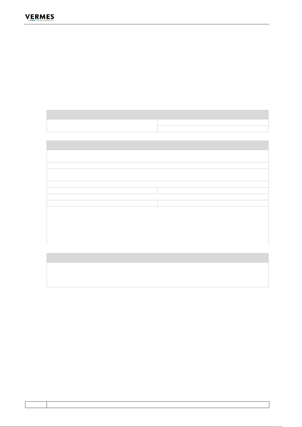
14.8 Declaration Concerning Decontamination of Shipped Equipment
Before returning Microdispensing Systems for purposes of inspection, maintenance and repair,
be sure that the equipment is in a completely decontaminated state. You have to fill out the
following form correctly; otherwise, the order will not be processed. Upon request, VERMES
Microdispensing performs the required decontamination after receipt of the corresponding
safety data sheet. This work will be calculated separately.
Only authorized and responsible personnel may fill out and sign this declaration!
1 Designation of the System
Serial No.:
MDV SN# _____________________________
MDV SN# _____________________________
2 Legally Binding Declaration
The signer declares that the microdispensing system is free of any substances harmful to health. The
decontaminated system is shipped according to legal prescriptions.
Company: _________________________________________________________________________
Address: __________________________________________________________________________
__________________________________________________________________________
Name: ____________________________________________________________________________
Phone: __________________________________
Fax:___________________________________
E-Mail: ____________________________________________________________________________
Date: ____________________________________
Signature: _____________________________
Company Stamp:
3 Note for Shipment
In order to prevent damage to the equipment, the manufacturer recommends using the original
packaging material for return. Instructions about transport have to be observed (see paragraph 12.1,
page 155). The manufacturer is not liable for any damage resulting from inadequate packaging or
transport.

List of figures
VTK-TR-BA-072e-1 - User Manual MDS 358X Series
175
15 List of figures
Fig. 1: Front Side ........................................................................................ 21
Fig. 2: Back Side ......................................................................................... 23
Fig. 3: Connection for power supply 48 V DC – pin functions ................ 24
Fig. 4: Main menu ....................................................................................... 27
Fig. 5: Menu structure ................................................................................ 28
Fig. 6: Display main menu ......................................................................... 29
Fig. 7: Submenu „Pulse Parameters“ ....................................................... 29
Fig. 8: Message “Heater connected - press enter” .................................. 30
Fig. 9: Submenu “Cooler/Heater” ............................................................. 30
Fig. 10: Submenu “Cooler” .......................................................................... 31
Fig. 11: Submenu “Heater” ......................................................................... 32
Fig. 12: Before reaching the target temperature ...................................... 32
Fig. 13: The target temperature is reached ............................................... 32
Fig. 14: Submenu “Status” .......................................................................... 34
Fig. 15: Submenu “Scenario” ...................................................................... 35
Fig. 16: Submenu “Scenario-Def. 1” ........................................................... 36
Fig. 17: Submenu “Service-Option” ........................................................... 37
Fig. 18: Composition .................................................................................... 39
Fig. 19: Explosion view valve ...................................................................... 41
Fig. 20: Content ............................................................................................ 44
Fig. 21: Distance of the bores 45 mm ......................................................... 50
Fig. 22: Connecting the actuator cable – step 1 ......................................... 51
Fig. 23: Connecting the actuator cable – step 2 ......................................... 51
Fig. 24: Connector actuator cable - grip .................................................... 51
Fig. 25: Connecting the sensor cable – step 1 ............................................ 52
Fig. 26: Connecting the sensor cable – step 2 ............................................ 52
Fig. 27: Connector sensor cable - grip ....................................................... 53
Fig. 28: Switching Power Supply 48 V 4 A Push-Pull and its connector ... 53
Fig. 29: Heater MDH-48-BY ......................................................................... 54
Fig. 30: Heater cable 48 V ............................................................................ 54
Fig. 31: Flow Control Valve FCV-AC 6.0 M12 .............................................. 54
Fig. 32: Connection Cable for FCV-AC/HF M12 to MDC ............................. 55
Fig. 33: Connection diagram of MDS 358X ................................................ 55
Fig. 34: Valve with air cooling connected .................................................. 56
Fig. 35: Screwing tight the nozzle fixation nut .......................................... 57
Fig. 36: Adjust – Press [ADJ] ........................................................................ 58
Fig. 37: Message Adjust Screw OUT ............................................................ 58
Fig. 38: Screw open adjust screw ................................................................ 58
Fig. 39: Adjust – Press [ENTER] .................................................................... 58
Fig. 40: Message 500 Shots – Please Wait .................................................. 59

List of figures
176
VTK-TR-BA-072e-1 - User Manual MDS 358X Series
Fig. 41: Message Please wait … .................................................................. 59
Fig. 42: Message Adjust Screw IN – until green LED .................................. 59
Fig. 43: Message Screw further IN .............................................................. 59
Fig. 44: Arrows displayed ............................................................................ 59
Fig. 45: Message press enter! – 0, the green adjust LED is ON ................. 59
Fig. 46: Adjust – Press Enter ........................................................................ 60
Fig. 47: Message Adjust Screw OUT – X <<<<, the red adjust LED is ON . 60
Fig. 48: System behavior ............................................................................. 64
Fig. 49: Select Pins ....................................................................................... 68
Fig. 50: Schematic of usage of select pins, example ................................. 68
Fig. 51: Circuit diagram ............................................................................... 69
Fig. 52: Scenarios of an MDC ....................................................................... 70
Fig. 53: Select Pins ....................................................................................... 72
Fig. 54: Schematic of usage of select pins .................................................. 72
Fig. 55: Submenu Service-Option ............................................................... 75
Fig. 56: MDH-48-BY ...................................................................................... 76
Fig. 57: Submenu Heater ............................................................................. 77
Fig. 58: Calibrator Set .................................................................................. 77
Fig. 59: FCV-AC 6.0 M12 ............................................................................... 80
Fig. 60: Submenu Cooler ............................................................................. 81
Fig. 61: Serial interface ................................................................................ 83
Fig. 62: PLC Interface: 15-pin, Sub-D ........................................................ 112
Fig. 63: Single-Shot Mode ......................................................................... 114
Fig. 64: Burst Mode (Example with Three Shots) ..................................... 114
Fig. 65: External Mode ............................................................................... 115
Fig. 66: Infinite Mode ................................................................................. 115
Fig. 67: PLC signals with Scenario OFF ..................................................... 116
Fig. 68: PLC signals with Scenario ON ...................................................... 116
Fig. 69: Screw open adjust screw .............................................................. 117
Fig. 70: AUX socket .................................................................................... 119
Fig. 71: Circuit diagram ............................................................................. 119
Fig. 72: Example - TTF Tappet (consists of tappet rod and tappet
spring) ........................................................................................... 138
Fig. 73: Example - Tappet Sealing PE ....................................................... 138
Fig. 74: Example - Nozzle Insert N11 ........................................................ 138
Fig. 75: EU Declaration of Conformity ...................................................... 164
Fig. 76: Dimensional Drawing MDC 3500 ................................................ 165
Fig. 77: Dimensional Drawing MDV 3580 front and sides ...................... 166
Fig. 78: Dimensional Drawing MDV 3580 positioning ............................ 167
Fig. 79: Connection Diagram PLC interface ............................................. 168
Fig. 80: Overview of the MDC Menu ......................................................... 169
Fig. 81: Connection Diagram MDS 3580 .................................................. 173