Vermes MDS 358X user Manual.pdf - 第79页
Operation 68 VTK - TR -BA- 072e - 1 - User Manua l MDS 358X S eries 7.8 Se lect Pins Se tups can be d irectly controlled vi a the s elect p ins of the AU X socket ( see F ig . 49 ), if “Scena rio ” in the submenu “ S cen…
Operation
VTK-TR-BA-072e-1 - User Manual MDS 358X Series
67
7.5 Input of Values
Modification of parameter values is simple. The name of the parameter appears in the upper, the
assigned numerical value in the lower line of the screen. If the last digit before the decimal point
is flashing, you can modify the value.
• Increase by one by using the [↑]-key.
• Correspondingly, the [↓]-key reduces the value by one.
• The [→]-key shifts the position of the active digit to the right.
• To shift the active position to the left, use the [←]-key.
Selection of other values (no numerical values) is performed similarly.
• Use the [→]-key or the [←]-key to change between ON and OFF.
• An input must be confirmed by [enter], to save the current selection. Then the control returns
to the next-higher menu point.
• To cancel without saving the current selection, press [esc]. The screen returns to the next-
higher menu level.
INFORMATION
Changing numbers
When modifying the first digit of a value from “1” to “0”, the cursor automatically jumps one
position to the right (if possible). The value in this position is set to 5, but you can modify it.
7.6 Saving Parameter Sets
Ten storage locations are available to save the pulse parameters from the menu.
– Step 1: Open the storage menu by pressing [save].
– Step 2: Select the desired storage location with the arrow keys.
– Step 3: Confirm the selection by pressing [enter].
INFORMATION
[esc] to abort
Pressing [esc] causes the saving procedure to be aborted. You can also use the submenu “Pulse
Parameters” (see paragraph 4.5.2, page 29) to save parameters.
7.7 Retrieving Parameter Sets
Parameter combinations saved in the system can be recalled any time.
– Step 1: Press [recall] to activate the corresponding function.
– Step 2: Select the desired storage location with the arrow keys.
– Step 3: Confirm the selection by pressing [enter].
INFORMATION
[esc] for interrupt
[esc] interrupts the procedure at once.
Operation
68
VTK-TR-BA-072e-1 - User Manual MDS 358X Series
7.8 Select Pins
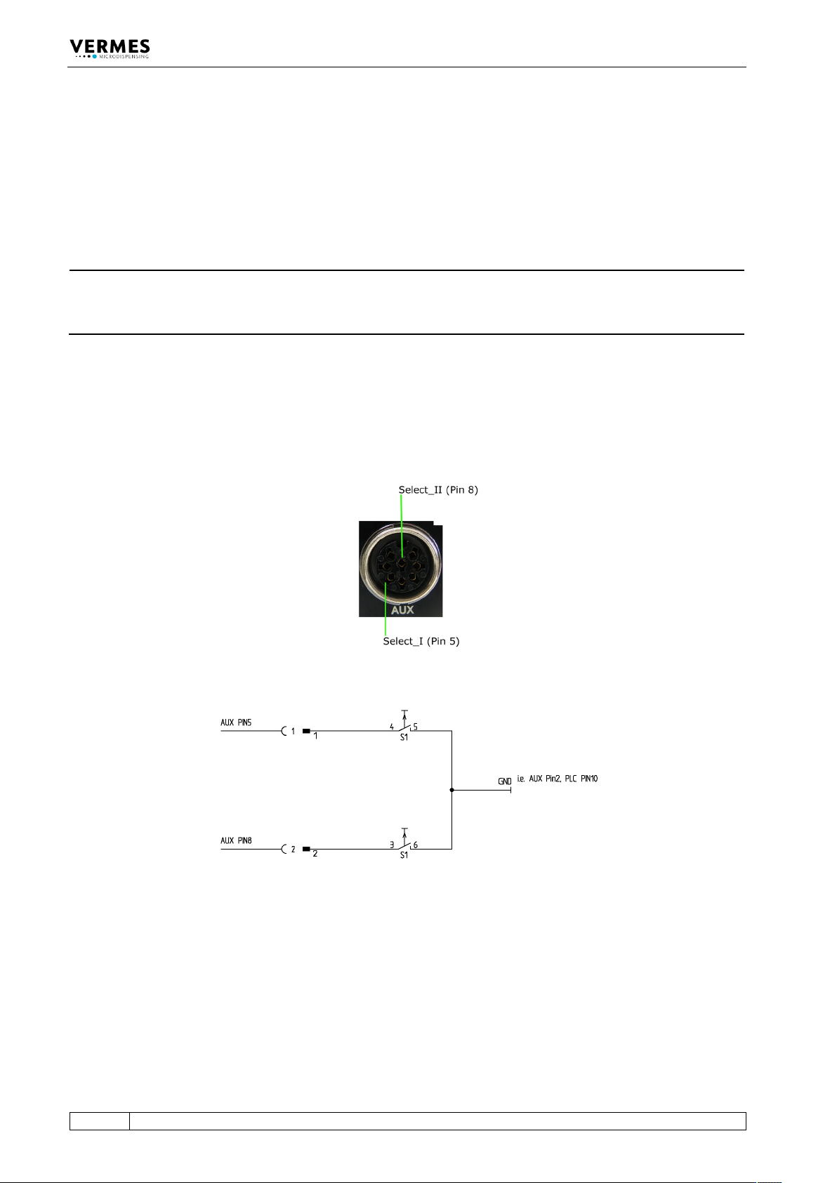
Setups can be directly controlled via the select pins of the AUX socket (see Fig. 49), if “Scenario”
in the submenu “Scenario” is turned “OFF”. (In case “Scenario” is “ON” and you want to work with
the scenarios, please refer to paragraph 7.9.3, page 71.) The select pins allow you to switch in real
time between the setups 0 to 3.
INFORMATION
Setup 0 = working configuration
Please be aware that setup 0 is the working configuration and therefore is not programmed
additionally.
With the pins Select_I (AUX socket Pin 5) and Select_II (AUX socket Pin 8) it is possible to switch
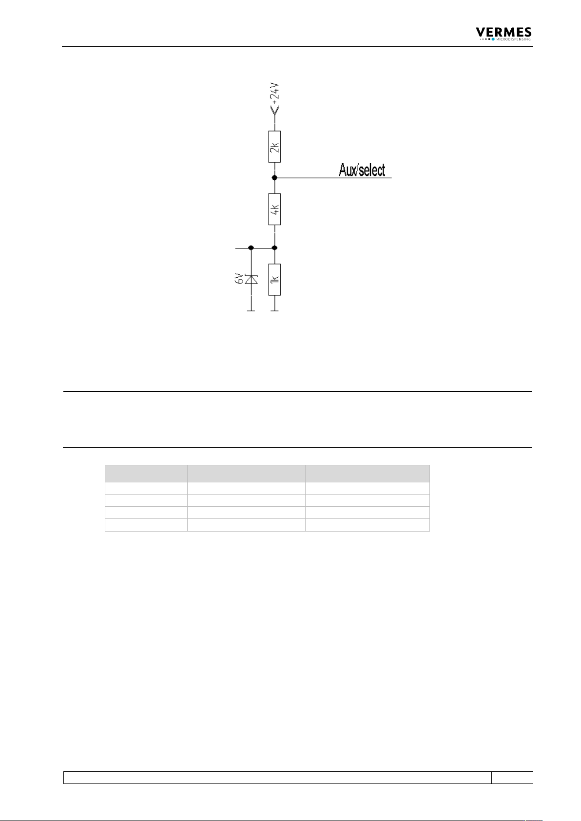
rapidly between different sets of parameters. In their blank state, the select pins are on a high
level (pull-ups to 24 V). You have to switch them to low (Gnd) to select a different setup (see Fig.
51, page 69 and see Tab. 22, page 69). For additional information regarding the AUX socket, see
paragraph 8.3, page 119. You have to switch them before triggering.
Fig. 49: Select Pins
Fig. 50: Schematic of usage of select pins, example
Operation
VTK-TR-BA-072e-1 - User Manual MDS 358X Series
69
Fig. 51: Circuit diagram
INFORMATION
Select pins with other commands
Select pins will be checked for triggering via PLC interface, for the serial commands
VALVE:AOPEN and SVALVE:AOPEN (in the versions without parameters) and when pressing the
[trig]-key.
Setup Select_II (Pin 8) Select_I (Pin 5)
Setup 0
High
High
Setup 1
Low
High
Setup 2
High
Low
Setup 3
Low
Low
Tab. 22: Select Pin settings for the setups