Vermes MDS 358X user Manual.pdf - 第70页
Initial Operation VTK - TR -BA- 072e - 1 - User Manua l MDS 358X S eries 59 Fig. 40 : Message 500 Sh ots – Please Wait A few sec onds lat er, t he dis play shows the m essage “P lease wai t …”. Fig. 41 : Message P lease …
Initial Operation
58
VTK-TR-BA-072e-1 - User Manual MDS 358X Series
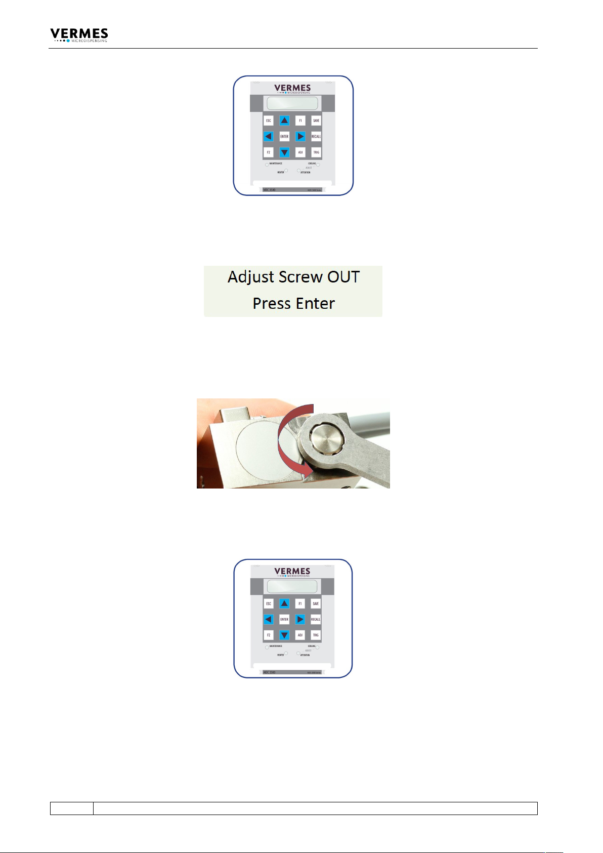
Fig. 36: Adjust – Press [ADJ]
The display shows the following message:
Fig. 37: Message Adjust Screw OUT
– Screw open the adjust screw completely (see Fig. 38; torque for screwing it open approx. 50 –
60 cN.m).
Fig. 38: Screw open adjust screw
– Afterwards press the [ENTER]-key.
Fig. 39: Adjust – Press [ENTER]
The display shows the message “500 Shots – Please Wait”. These shots help to prepare the valve
for the adjust.
Initial Operation
VTK-TR-BA-072e-1 - User Manual MDS 358X Series
59
Fig. 40: Message 500 Shots – Please Wait
A few seconds later, the display shows the message “Please wait …”.
Fig. 41: Message Please wait …
Wait until a new message on the display announces the next step.
Adjust, step 2 (Turn in adjust screw):
The screen shows the message “Adjust Screw IN until green LED”.
Fig. 42: Message Adjust Screw IN – until green LED
After one second, the initial message disappears from the display. Instead, the message “Screw
further IN” appears.
Fig. 43: Message Screw further IN
– Screw the adjust screw carefully clockwise. While screwing, you will see an increasing amount
of arrows shown in the display (see Fig. 44).
Fig. 44: Arrows displayed
Adjust, step 3 (Find adjust point and confirm it):
– Keep turning the adjust screw slowly clockwise, until the display shows “press enter! - 0”.
Meanwhile, the green adjust LED is ON (see Fig. 45).
Fig. 45: Message press enter! – 0, the green adjust LED is ON
Initial Operation
60
VTK-TR-BA-072e-1 - User Manual MDS 358X Series
– Confirm the adjust with pressing [ENTER]. The adjust is finished successfully and you are send
back to the main menu.
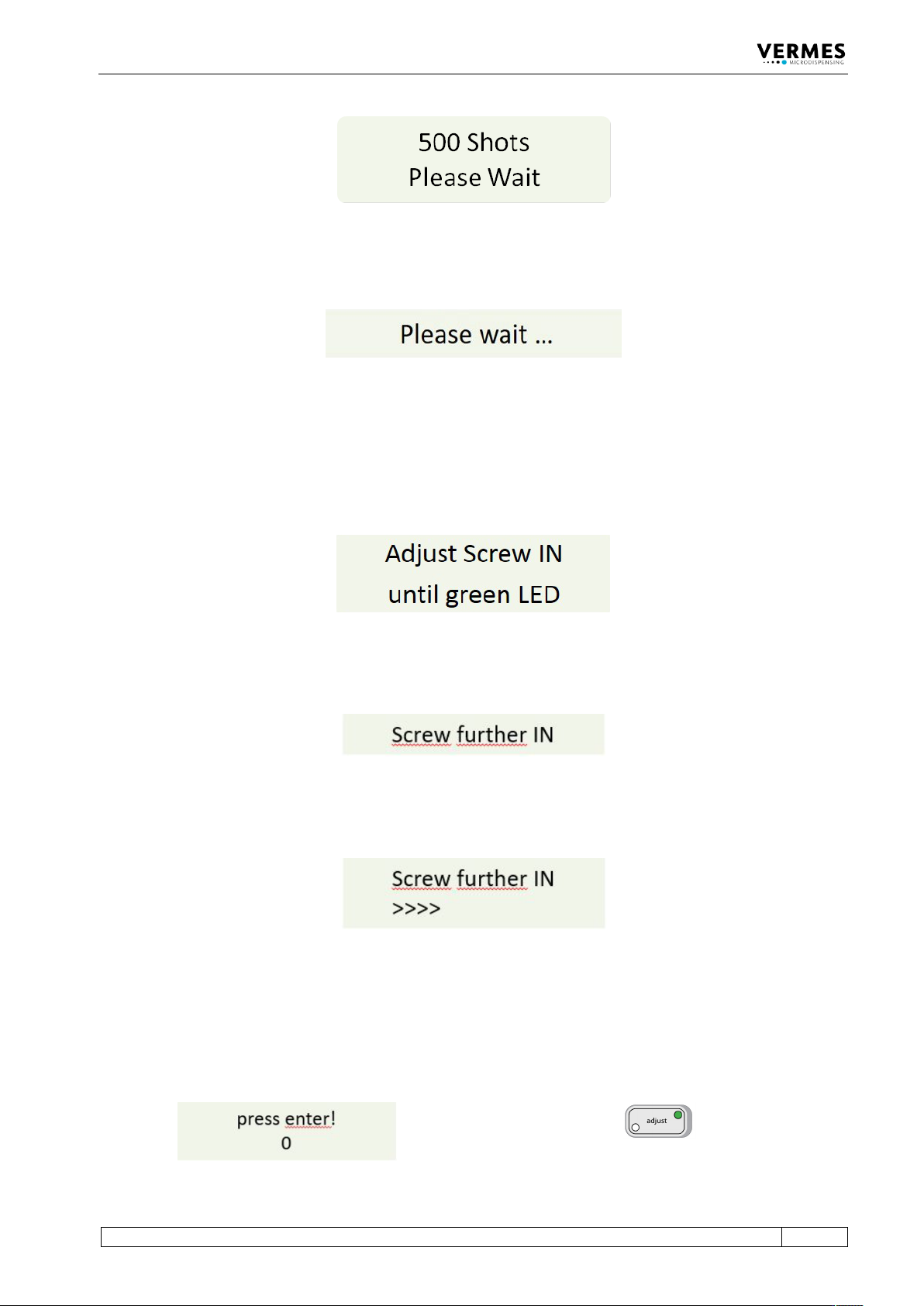
Fig. 46: Adjust – Press Enter
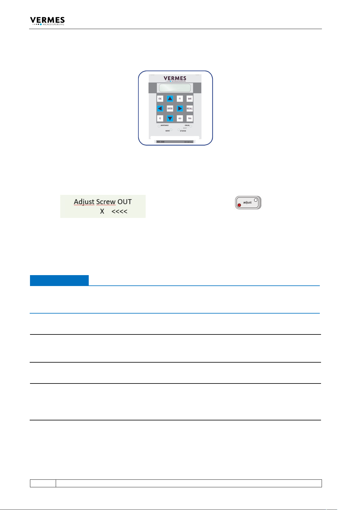
In case you had turned the adjust screw too far, the display shows “Adjust Screw OUT – X <<<<”.
Also, the red adjust LED is ON instead of the green one (see Fig. 47).
Fig. 47: Message Adjust Screw OUT – X <<<<, the red adjust LED is ON
– Unscrew the adjust screw (counter-clockwise) until the display shows “press enter! - 0” and
the green adjust LED is ON.
– Press the [ENTER]-key.
IMPORTANT NOTE
Do not screw too far
Do not keep screwing the adjust screw further clockwise, if the red adjust LED is ON. Otherwise
the tappet or the nozzle insert could get damaged.
INFORMATION
Confirming adjust
A correctly completed adjust can only be confirmed with [ENTER], while the green adjust LED is
ON.
INFORMATION
Abort and end of procedure
• The adjust can be aborted any time by pressing [ESC]. The display changes back to the main
menu.
• After the adjust the green lamp dims within approx. 3 s.