Vermes MDS 358X user Manual.pdf - 第130页
Communication Interfaces VTK - TR -BA- 072e - 1 - User Manua l MDS 358X S eries 119 8.3 AUX socket The AUX socket can b e used for the sup ply of an ext ernal device (e.g. an optocoupler ) or to contr ol cert ain set ups…
Communication Interfaces
118
VTK-TR-BA-072e-1 - User Manual MDS 358X Series
• 5 V or 24 V (PIN2 + PIN4 or PIN3 + PIN4 Input signal of MDC via 15 pin Sub-D)
• Signal length: 500 μs – 80 ms
3. The system jets 500 shots to clear the valve for the remote adjust. The message “500 Shots
Please Wait” is shown. Then the message “Please wait…” appears.
4. The message “Adjust Screw IN until GREEN LED ON” appears first. Then the message
alternates with “SLOW-SCREW IN until green LED ON”. The system then returns the current
status of the adjust LEDs, continuously repeating the transmission to the PC in intervals of 500
ms (via RS-232C). An additional command to update the status of the adjust LEDs on the
screen is not required.
5. Turn the adjust screw inwards (clockwise), until the message displayed on the PC is changed
to “Adjust LED GREEN press enter”. The green adjust LED on the MDC is lit.
6. In order to confirm the remote adjust, send a short trigger signal (500 μs – 80 ms) to the
control unit via PLC interface (see Step 2). This will only be accepted, if the message “Adjust
LED GREEN press enter” is shown. After the confirmation, the system then returns the
following response via RS-232C: “Adjust Success”.
The remote adjust has been completed successfully.
In case you had turned the adjust screw too far, the message “Adjust LED RED Adjust Screw OUT”
appears. Turn the adjust screw outwards (counter-clockwise), until the message “Adjust LED
GREEN press enter” appears. Confirm the remote adjust as described (see Step 6).
The remote adjust can be aborted anytime by sending a long trigger signal (110 ms – 200 ms) to
the control unit via PLC- interface. The system returns the message “Adjust failed” to the PC.
Long trigger signal:
• 5 V or 24 V (PIN2 + PIN4 or PIN3 + PIN4 Input signal of MDC via 15 pin Sub-D)
• Signal length: 110 ms – 200 ms
INFORMATION
Remote adjust deactivates heater and cooling
In case heater or cooling are still ON, they will be automatically deactivated by a remote adjust.
After you have performed the remote adjust, the cooling will be automatically switched back to
the ON/OFF status before the remote adjust. But the heater needs to be turned ON again
manually, if you need it for your application.
Communication Interfaces
VTK-TR-BA-072e-1 - User Manual MDS 358X Series
119
8.3 AUX socket
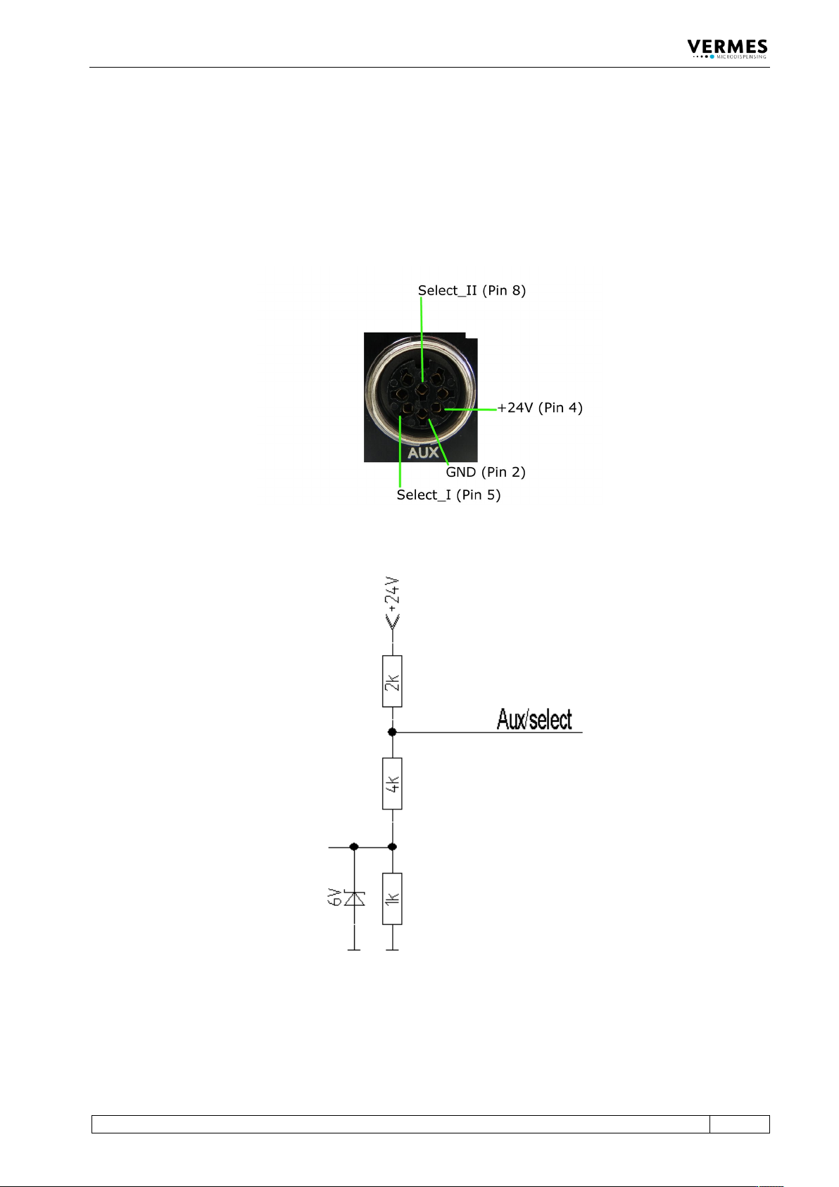
The AUX socket can be used for the supply of an external device (e.g. an optocoupler) or to
control certain setups (see paragraph 7.8, page 68) or scenarios (see paragraph 7.9, page 70). The
pin assignments are shown below (see Fig. 70). In case the select pins are activated, the
maximum current is 12 mA. The other pins are used internally and cannot be used otherwise. The
socket is a Lumberg SV81 8P.
Fig. 70: AUX socket
Fig. 71: Circuit diagram
Cleaning
120
VTK-TR-BA-072e-1 - User Manual MDS 358X Series
9 Cleaning
After every dispensing process involving aggressive or self-curing substances, a cleaning
procedure is recommended. It should involve the valve and all other surfaces in contact with the
fluid. Different methods of cleaning are described in the following chapter. The proper choice
depends on the degree of contamination and the dispense medium used.
9.1 Preliminary Notes
IMPORTANT NOTE
Prepare cleaning in advance
It is recommended to prepare the cleaning procedure in advance. Do not drop the device or its
subcomponents.
CAUTION
Liquid spurts possible
Residual liquids may spurt when handling components during the cleaning process. Therefore,
protective clothes are recommended:
• Safety goggles
• Gloves (chemical resistant)
• Overall (chemical resistant)
• Surgical mask
Remember that the surface of the valve is sensitive to abrasion, so do not use wire brushes and
other inappropriate tools. A specially developed cleaning tool kit (CTK 2.5) is available upon
request (order no. 1014632), which is of particular interest for all surfaces in direct contact with
the fluid.
WARNING
Potential chemical reaction!
The dispensed medium and the cleaning agent must be compatible to each other. Otherwise,
they might cause unwanted chemical reactions, toxic vapor, increase of temperature etc. Consult
the manufacturer in case of doubt.
Before introducing aggressive purifying agents or solvents to the system, verify compatibility
with the material of all adjacent parts. Refer to the list in Page 122.
In case of materials you cannot find on the list, please consult the manufacturer or the Technical
Support of VERMES Microdispensing (see Page 7).
CAUTION
Keep actuator clean
No liquid may penetrate into the actuator (e.g. through the plug); otherwise the whole element
could be damaged.