Vermes MDS 358X user Manual.pdf - 第127页
Communication Interfaces 116 VTK - TR -BA- 072e - 1 - User Manua l MDS 358X S eries 8.2.2.5 Comparison of the signals DosOK and SingleDo sOK for S cenario ON an d Scenario OFF The follow ing two fi gures show the si gnal…
Communication Interfaces
VTK-TR-BA-072e-1 - User Manual MDS 358X Series
115
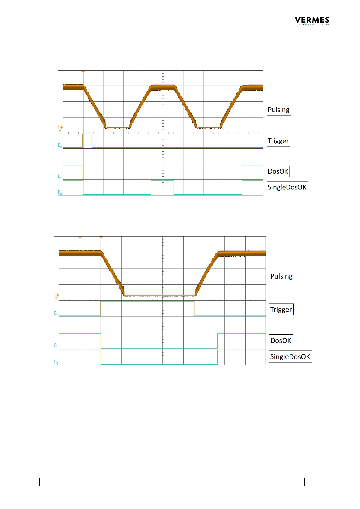
8.2.2.3 External Mode
Fig. 65: External Mode
8.2.2.4 Infinite Mode
Fig. 66: Infinite Mode
Communication Interfaces
116
VTK-TR-BA-072e-1 - User Manual MDS 358X Series
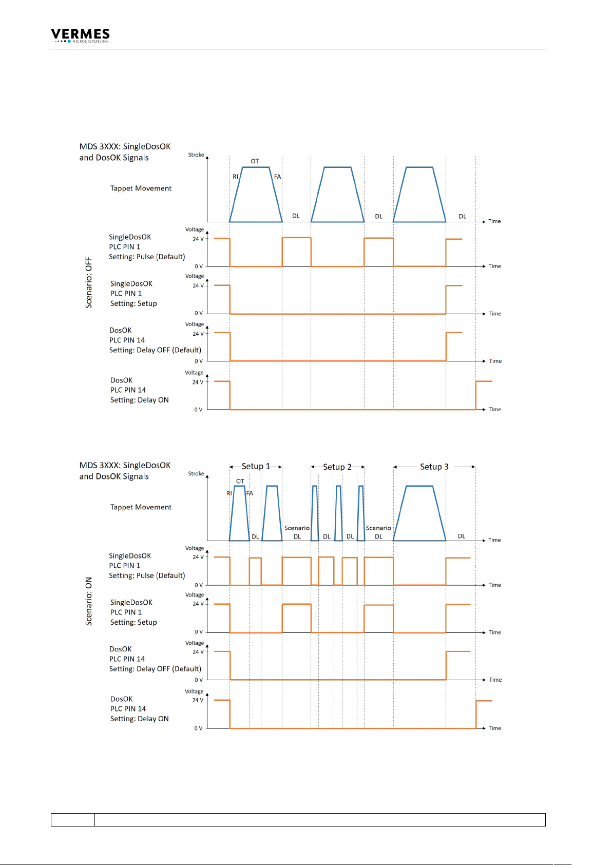
8.2.2.5 Comparison of the signals DosOK and SingleDosOK for Scenario ON and Scenario OFF
The following two figures show the signals DosOK and SingleDosOK in relation to the tappet
movement. In the first figure, scenarios are off, in the second figure, scenarios are ON.
Fig. 67: PLC signals with Scenario OFF
Fig. 68: PLC signals with Scenario ON
Communication Interfaces
VTK-TR-BA-072e-1 - User Manual MDS 358X Series
117
Yuki mas nani tipper cat 1
8.2.3 Remote Adjust
8.2.3.1 What is the Remote Adjust?
A remote adjust is similar to a normal adjust (see paragraph 6.5, page 57), but the system is
operated from a master device (e.g. a PC or an XY machine) by means of interfaces (PLC, RS-
232C). The function itself is identical.
8.2.3.2 Advantages
The remote adjust allows for total control of an MDC integrated in a machine, since dispensing
parameters can be monitored by the software of this machine. The control unit can be built in
with permanent key lock. Thus the modification of parameters without authorization can be
prevented in the machine software.
8.2.3.3 Procedure
The remote adjust has to be performed according to the following instructions:
INFORMATION
Displaying remote adjust
• In the beginning of the remote adjust, both adjust LEDs are lit simultaneously.
• The display of the MDC shows “Remote Adjust is running!”
• For transmission of the orders between PC and control unit, the interfaces RS-232C and PLC-
interface are used.
INFORMATION
Preparation before remote adjust
• Screw the nozzle fixation nut absolutely tight (torque at least 150 cN.m).
• The baud rate of the serial interface needs to be set to 115200.
1. Send the command “ADJUST:START” to the control unit via RS-232C. The system returns the
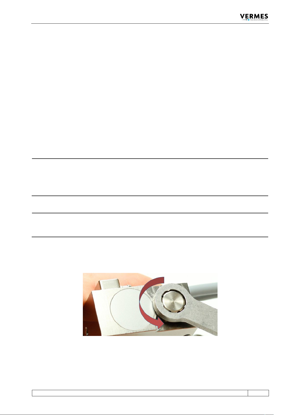
message “Adjust Screw OUT Press Enter”. Screw open the adjust screw completely (counter-
clockwise, see Fig. 69, torque for screwing it open is approx. 50 – 60 cN.m).
Fig. 69: Screw open adjust screw
2. In order to confirm step 1, send a short trigger signal (500 μs – 80 ms) to the control unit via
PLC interface.
Short trigger signal: