Vermes MDS 358X user Manual.pdf - 第34页
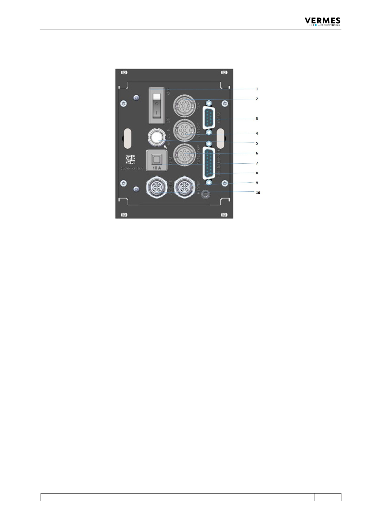
Control Unit MDC VTK - TR -BA- 072e - 1 - User Manua l MDS 358X S eries 23 4.3 Back Sid e Fig . 2: Back Side 1 ON/OFF s wi tch 2 AUX socket 3 RS - 232C int erface (9 - pin) 4 Sens or socket 5 Pow er conn ection 6 Actuato…

Control Unit MDC
22
VTK-TR-BA-072e-1 - User Manual MDS 358X Series
Outside of the adjust, it indicates the intensities of cooling (for details, see paragraph 4.5.3.1,
page 31).
• More effective cooling, once the actuator temperature goes over 10 °C above the target
temperature - LED flashes
• “normal” cooling, if the actuator temperature is within 10 °C above the target temperature -
LED ON
Be aware that the ON/OFF status of the cooler is not shown by means of this lamp.
Control lamp for attention/adjust (red):
This red LED has two purposes.
During the adjust, the LED lights up, if you screw the adjust screw too far. You have to screw it
out according to the instructions of this manual (see paragraph 6.5 "The Adjust Process",
page 57).
Outside of the adjust, the LED is ON, whenever the MDC has detected an error.
Control lamp for status of heating:
This red LED indicates the activity of the heating (for more details, see paragraph 4.5.3.2,
page 31).
The heater is ON, and the target temperature is reached and stable – LED ON
The heater is deactivated – LED OFF
The heater is ON, but the target temperature is not yet reached – LED flashes
Control Unit MDC
VTK-TR-BA-072e-1 - User Manual MDS 358X Series
23
4.3 Back Side
Fig. 2: Back Side
1 ON/OFF switch
2 AUX socket
3 RS-232C interface (9-pin)
4 Sensor socket
5 Power connection
6 Actuator socket
7 10 A fuse
8 PLC interface (15-pin)
9 Socket for cooling
10 Socket for heating
ON/OFF switch:
By means of this switch, the unit is switched ON and OFF.
AUX socket:
This connector can be used for supply of an external device (e.g. an optocoupler) or to control
certain parameter setups or scenarios paragraph 8.3, page 119. It is one of the three interfaces of
the control unit (see Page 83 for the pin assignments).
RS-232C interface (9-pin):
Since the system offers the possibility of external programming of dispensing parameters via PC,
a local RS-232C is integrated to receive the data. For the communication protocol, refer to see
Fig. 3, page 24.
Sensor socket:
For the connection of the sensor cable.
Power connection:
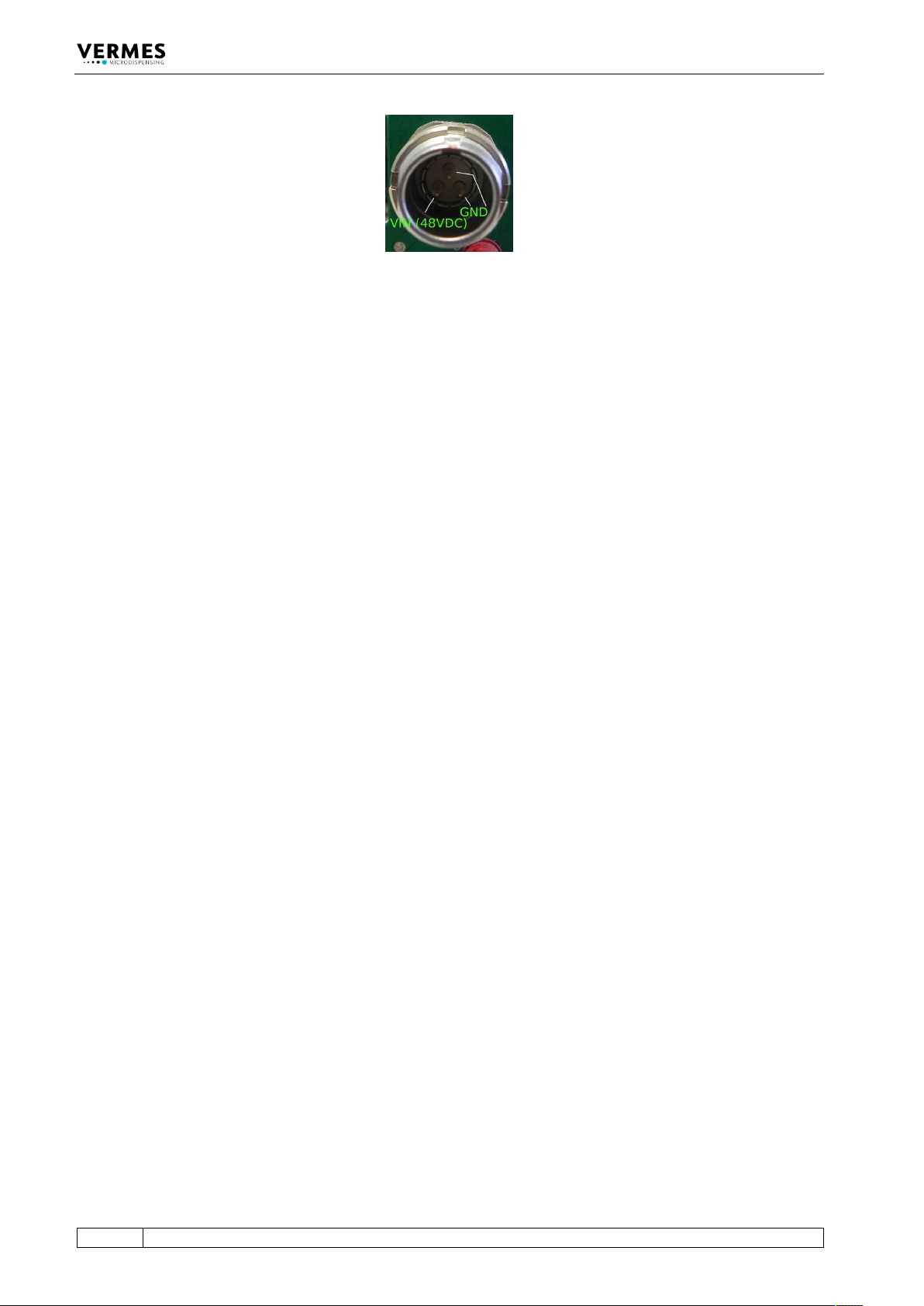
Connects the control unit to power via an external power supply. The MDC needs 48 V DC. For
information regarding the pin functions, Page 113.
Control Unit MDC
24
VTK-TR-BA-072e-1 - User Manual MDS 358X Series
Fig. 3: Connection for power supply 48 V DC – pin functions
Actuator socket:
For the connection of the actuator cable.
10 A fuse:
For the protection of the electronic parts inside of the control unit.
PLC interface (15-pin):
Different inputs and outputs may be connected. For the communication protocol, refer to (see
paragraph 7.8 "Select Pins", page 68).
Socket for cooling:
The connection cable for FCV (for the valve cooling) has to be connected here.
Socket for heating:
The heater cable has to be connected here.